Transducer sheet sealing structure for ultrasonic atomizer

A sealing structure and atomizer technology, which is applied in the direction of fluid, spraying device, liquid spraying device using vibration, etc., can solve the problems of inconvenient disassembly, poor sealing effect, damage to the transducer, etc., so as to achieve convenient and safe installation. The effect of good sealing effect and simple assembly

Inactive Publication Date: 2007-06-06
KERI ELECTRONICS GUICHENG NANHAI CITY
View PDF2 Cites 7 Cited by
  • Summary
  • Abstract
  • Description
  • Claims
  • Application Information

AI Technical Summary

Problems solved by technology

The sealing structure of a sealing ring is adopted, not only the whole atomization generator cannot be placed in water and other liquids for use, but if the whole atomization generator is placed in water and other liquids for use, water and other liquids will seep into the housing from the lower plastic seat, which has a sealing effect Not good, and according to the structure adopted in the application, it is extremely inconvenient to disassemble when replacing the transducer
[0003] The Chinese patent number is 02227246.1, the publication date is March 12, 2003, and the invention name is "Gland Structure of Ultrasonic Spray Head". The application discloses a gland structure of ultrasonic spray head, as shown in Figure 1 , including a housing 1, a cavity 2 with an upper opening, a spring on the bottom of the cavity, and a transducing sheet 4 on it, a gland 3 screwed into the upper opening of the cavity, pressing the transducing sheet 4, and the periphery of the transducing sheet 4 A sealing ring 5 is provided, and a sealing ring 6 is also provided at the contact portion between the gland 3 and the upper end of the housing 1. With such a structure, although it can prevent liquid from penetrating into the threaded connection between the gland and the housing, thereby avoiding the It is difficult to unscrew the gland due to the sedimentation of scale; however, adopting such a structure will also produce the following defects: (1) Since the two sealing rings are pressed synchronously with the same gland 3, the housing 1 and The cooperation precision between the gland 3, the transducer plate 4 and the gland 3 and the corresponding sealing ring must be very high, otherwise it is difficult to achieve a consistent pace, and one of the sealing rings may be pressed tightly, while the other sealing ring It has not been compressed yet, resulting in poor sealing effect of the entire ultrasonic nebulizer
(2) The transducer is pressed on the spring. During the loading and unloading process, after removing the gland first, due to the elastic effect of the spring, the transducer may be ejected and damaged

Method used


Image

  • Transducer sheet sealing structure for ultrasonic atomizer
  • Transducer sheet sealing structure for ultrasonic atomizer
  • Transducer sheet sealing structure for ultrasonic atomizer

Examples


Embodiment 1

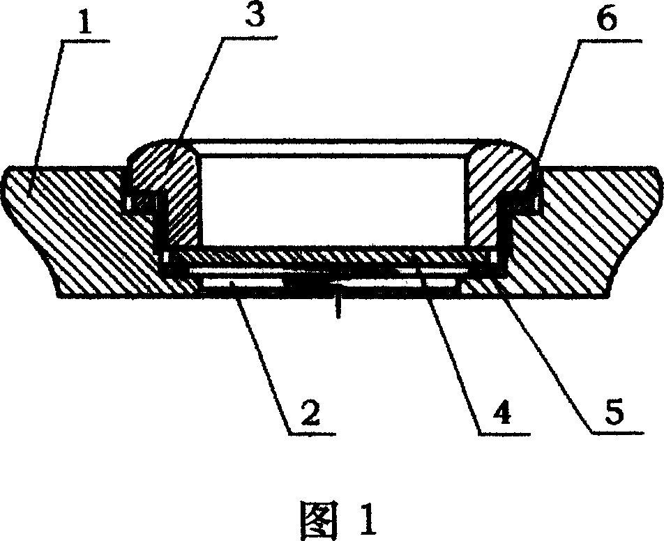
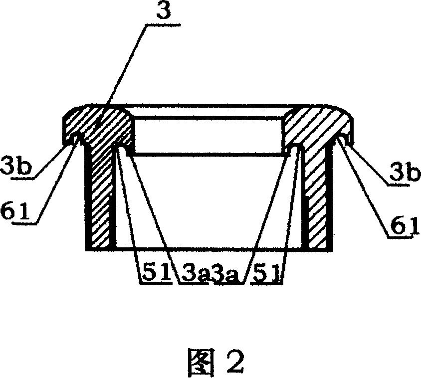
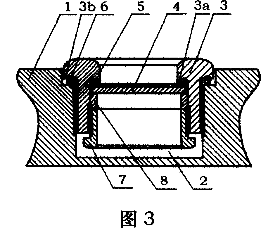
[0023] Embodiment 1: As shown in Figure 3, the ultrasonic atomizer includes a housing 1, and a cavity 2 is arranged on the housing 1; secondly, a control circuit can also be provided in the housing 1, and the control circuit and the transducer plate To electrically connect and drive the transducer sheet, of course, the control circuit can also be arranged outside the casing 1 . The annular gland 3 has a T-shaped inner flange 3a and an outer flange 3b, and an annular groove 51 is provided on the inner flange 3a corresponding to the position of the transducer seal ring 5, and the transducer seal ring 5 is inserted into the annular groove within 51. An outer annular groove 61 is arranged on the position corresponding to the gland sealing ring 6 on the outer flange 3b, and the gland sealing ring 6 is embedded in the outer annular groove 61; the outer wall of the annular gland 3 is provided with threads, and the inner wall of the cavity 2 is provided with The thread that is matche...

Embodiment 2

[0024] Embodiment 2: On the basis of Embodiment 1, the connection relationship between the ring-shaped fixing seat 7 and the ring-shaped gland 3 is set as four screws 9 that are symmetrically distributed by thread fit connection, as shown in Figure 4, and the rest of the structures are the same as The connection relationship is the same as that in Embodiment 1.


PUM


Abstract

The present invention relates to one kind of transducer sheet sealing structure for ultrasonic atomizer, and aims at providing one kind of transducer sheet sealing structure with good sealing effect and convenient installation. The transducer sheet sealing structure includes one cavity in the casing, one ring gland with T-shaped cross section and embedded into the cavity, one transducer sheet set inside the ring gland, sealing rings, and one ring fixing seat inside the ring gland. It can realize the sealing between the transducer sheet and the ring gland. The present invention is suitable for different kinds of ultrasonic atomizer.

Description

technical field [0001] The invention relates to a sealing structure of an ultrasonic nebulizer, in particular to a sealing structure of a transducer sheet of the ultrasonic nebulizer. Background technique [0002] The sealing structure of the transducer sheet of the existing ultrasonic atomizer is generally composed of a casing, a cavity arranged on the casing, a transducer sheet, a sealing ring and a transducer sheet gland. The Chinese patent number is 90218828.3, and the date of announcement is April 10, 1991. The name of the invention is "A Piezoelectric Ceramic Atomizing Nozzle". The application discloses a piezoelectric ceramic atomizing nozzle, which uses a sealing ring to The direct sealing structure between the transducer sheet and the housing. The sealing structure of a sealing ring is adopted, not only the whole atomization generator cannot be placed in water and other liquids for use, but if the whole atomization generator is placed in water and other liquids for...

Claims


Application Information

Patent Timeline
Patent Type & Authority Applications(China)
IPC IPC(8): B05B17/06B06B1/06
Inventor 余志英
Owner KERI ELECTRONICS GUICHENG NANHAI CITY
Why Eureka
Try Eureka