
Robot control device and robot system

A robot system and control device technology, applied in the direction of manipulators, manufacturing tools, etc., can solve the problems of expanding the extension area of ​​cables and increasing the occupied area of ​​robot systems

Active Publication Date: 2007-06-06
SEIKO EPSON CORP
View PDF2 Cites 2 Cited by
  • Summary
  • Abstract
  • Description
  • Claims
  • Application Information

AI Technical Summary

Problems solved by technology

As a result, the area where the cables protrude from the robot controller expands, thereby increasing the footprint of the robot system

Method used


Image

  • Robot control device and robot system
  • Robot control device and robot system
  • Robot control device and robot system

Examples


Embodiment Construction

[0017] Next, an embodiment of the present invention will be described with reference to FIGS. 1 to 3 .

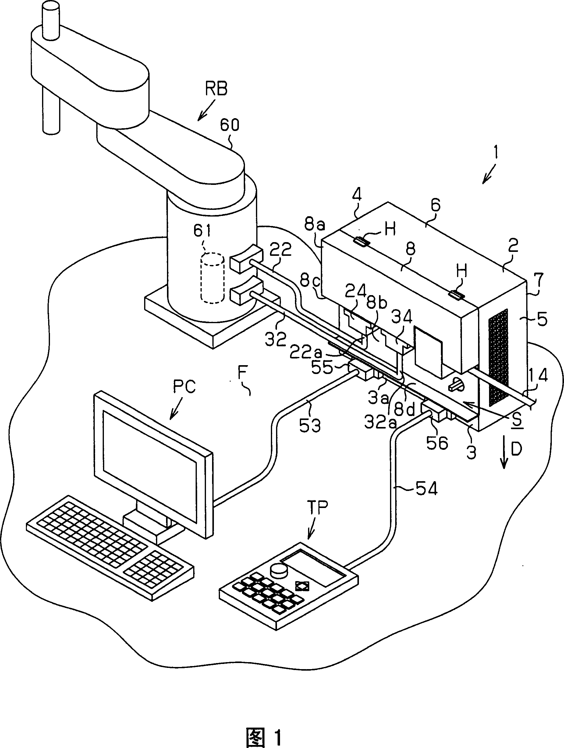
[0018] As shown in FIG. 1 , the robot system has an industrial robot RB and a controller 1 as a robot control device that drives the robot RB. The industrial robot RB includes a four-axis control type horizontal multi-joint robot arm 60 and a motor 61 as an actuator for driving the robot arm 60 .

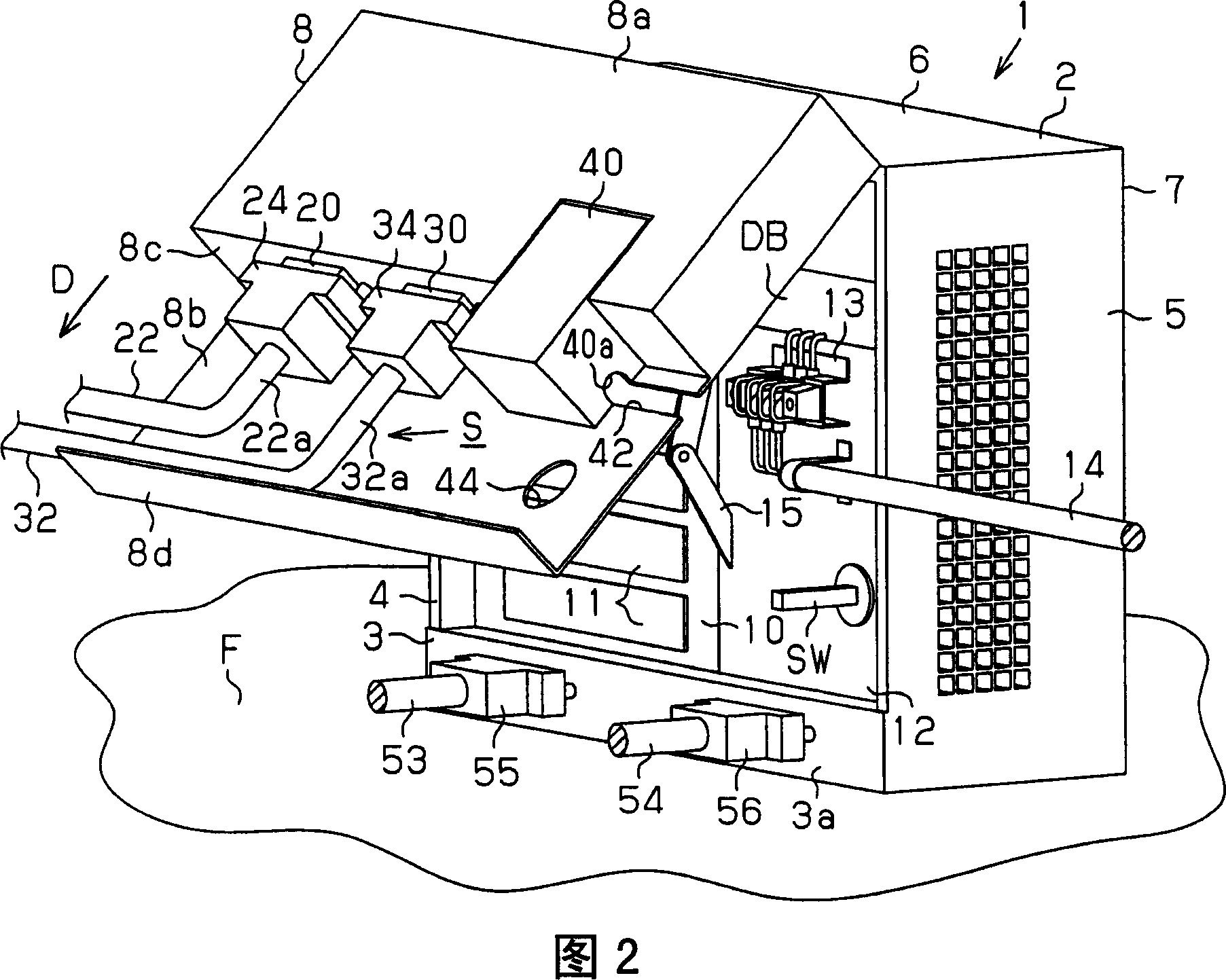
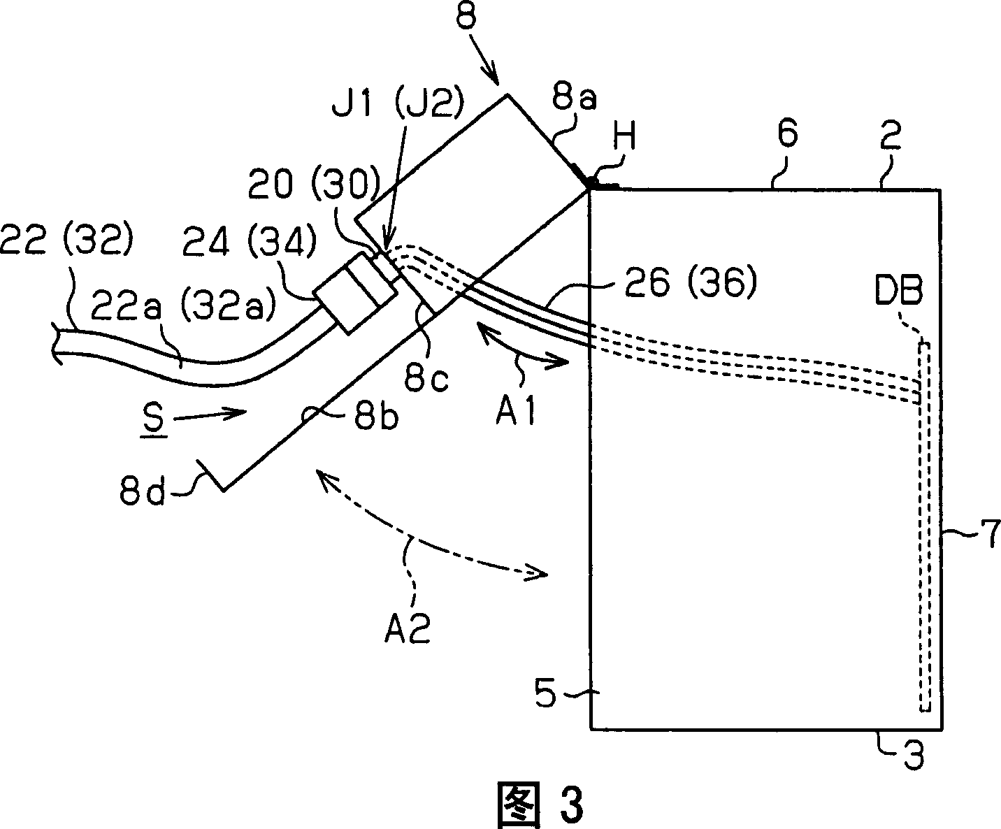
[0019] The controller 1 has a rectangular parallelepiped housing 2 installed on the installation surface F. As shown in FIG. The box body 2 has: a base 3 disposed on the installation surface F, a left plate 4 disposed on the left end of the base 3, a right plate 5 disposed on the right end of the base 3, a left plate 4 and a right plate The top plate 6 of 5 upper ends. The box body 2 also has: a back panel 7 closing the rear opening of the space surrounded by the base 3, the left panel 4, the right panel 5 and the top panel 6, and an opening and closing control panel 8 capable ...


PUM


Abstract

A robot control device is connected to an industrial robot through a connection cable. The robot control device has a casing that accommodates an actuator controller. A side surface of the casing has a stepped portion. The stepped portion includes a connecting portion located in such a manner that the connection cable extends along the side surface while arranged on the side surface. The connection cable is connected to the connecting portion. This configuration saves space of the robot control device.

Description

technical field [0001] The invention relates to a robot control device and a robot system. Background technique [0002] Generally, an industrial robot system has a robot control device connected to the industrial robot through a power cable or a signal cable. The industrial robots disclosed in JP-A-2001-67110 and JP-A-2000-66706 receive a signal output from a robot controller and perform processing operations corresponding to the signal. [0003] In recent years, from the viewpoint of saving space in production equipment, reduction in the occupied space of robot systems has been strongly desired. However, as the number of joints of an industrial robot such as a horizontal multi-joint or a vertical multi-joint increases, the number of actuators for driving the joints also increases. As a result, the diameter of the cable for connecting the actuator to the robot controller becomes thicker. [0004] When pulling out the cable from the robot controller while drawing it in a ...

Claims


Application Information

Patent Timeline
Patent Type & Authority Applications(China)
IPC IPC(8): B25J13/00B25J19/00
Inventor 平林友一
Owner SEIKO EPSON CORP
Learn More