Light permanent form for concrete filling

A permanent tire, lightweight technology, used in building components, floors, buildings, etc., can solve the problems of high cost, low production efficiency, inconvenient production and production, and achieve the purpose of preventing floating displacement, improving stiffness and strength, and easy pouring. The effect of tamping and compacting

Inactive Publication Date: 2007-06-06
湖南邱则有专利战略策划有限公司
View PDF1 Cites 0 Cited by
  • Summary
  • Abstract
  • Description
  • Claims
  • Application Information

AI Technical Summary

Problems solved by technology

This formwork member has the characteristics of simple structure and convenient construction and transportation. After being applied to the floor, there is no force-bearing and force-transmitting member of the floor in the formwork member, especially when the formwork member is larger in size, the p

Method used


Image

  • Light permanent form for concrete filling
  • Light permanent form for concrete filling
  • Light permanent form for concrete filling

Examples


Example Embodiment

[0081] The present invention will be further described below in conjunction with the accompanying drawings and embodiments.

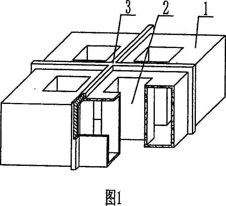
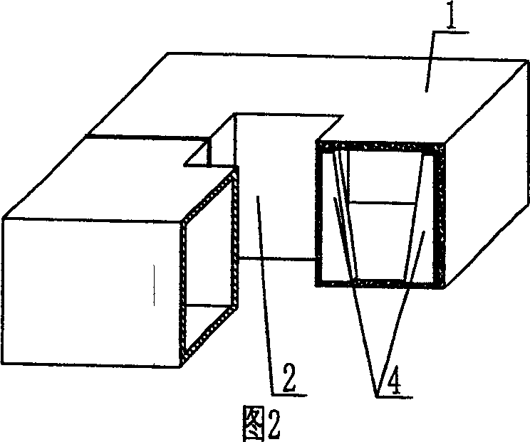
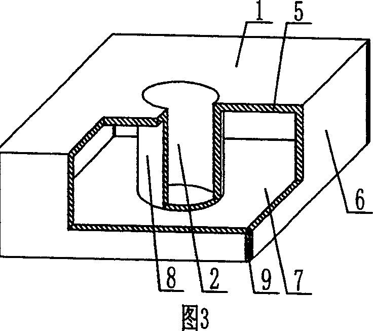
[0082] As shown in the accompanying drawings, the present invention comprises a lightweight carcass 1, the lightweight carcass 1 includes an upper shell 5, surrounding side shells 6, and a lower shell 7, and the upper shell 5, surrounding side shells 6, and lower shells 7 form a closed space. The cavity is characterized in that it also includes a through-hole tube 8, which is arranged in the closed cavity of the lightweight carcass 1, and there is at least one existing hole formed by the through-hole tube 8 in the light-weight carcass 1. The hole 2 for pouring concrete runs through the surface of the upper and lower shells of the lightweight carcass 1, the through-hole pipe 8, the lower shell 7, and the surrounding side shells 6 are an integral bottom shell 20, and the upper shell 5 is combined with the integral bottom shell 20, and the upper shell 5. S...


PUM


Abstract

The present invention relates to a light permanent form for filling concrete. It includes light form body. Said light form body includes upper plate, peripheral side plate and lower plate which are mutually connected together and formed into a closed hollow cavity. It is characterized by that it also includes a tube for making through hole, and said tube for making through hole is placed in the closed hollow cavity. Said light permanent form can be used for in-situ casting reinforced concrete or prestressed reinforced concrete hollow floor, roof, wall body, foundation bedplate and open-web bridge, etc.

Description

(1) Technical field [0001] The invention relates to a lightweight permanent carcass for concrete filling. (2) Background technology [0002] At present, the cast-in-place concrete hollow floor is a widely used floor structure. The lightweight permanent tire molds filled in it include various hollow tubes and boxes, and the boxes are hollow or solid. For example, the patent No. ZL99249798.1, which the applicant applied for on November 29, 1999, is a utility model patent named "fiber-reinforced thin-walled member for reinforced concrete filling", which discloses a thin-walled formwork member, including an upper plate, The surrounding side walls, the lower bottom, the upper plate, the surrounding side walls, and the lower bottom form a polyhedral cavity, and the upper plate, the surrounding side walls, and the lower bottom contain fiber reinforcements. This formwork member has the characteristics of simple structure and convenient construction and transportation. After being a...

Claims


Application Information

Patent Timeline
IPC IPC(8): E04B5/16E04B5/36E04C1/00
Inventor 邱则有
Owner 湖南邱则有专利战略策划有限公司
Why Eureka
Try Eureka