Reinforced reinforced concrete frame joints

A reinforced concrete and reinforced technology, applied in the direction of building, building structure, etc., can solve the problems of insufficient seismic performance such as bearing capacity and ductility, dense reinforcement in node areas, and complex construction technology, so as to reduce the phenomenon of reinforcement density and reduce The number of hoops and the effect of improving the shear bearing capacity of the joints

Active Publication Date: 2020-04-24
HUBEI ENG UNIV
View PDF11 Cites 0 Cited by
  • Summary
  • Abstract
  • Description
  • Claims
  • Application Information

AI Technical Summary

Problems solved by technology

[0004] The purpose of the present invention is to solve the complex construction process of ordinary reinforced concrete frame joints, intensive reinforcement in the joint area, difficulty in pouring compaction, insufficient seismic performance such as bearing capacity and ductility, and failure to meet the requirements of "strong shear weak bending, strong column weak beam, strong column weak beam, etc. "Strong joint" requirements and other issues, overcome the shortcomings of the existing technology, and provide a reinforced reinforced concrete frame joint

Method used


Image

  • Reinforced reinforced concrete frame joints
  • Reinforced reinforced concrete frame joints
  • Reinforced reinforced concrete frame joints

Examples


Embodiment Construction

[0026] The present invention will be described in further detail below in conjunction with the accompanying drawings and specific embodiments, so that those skilled in the art can understand.

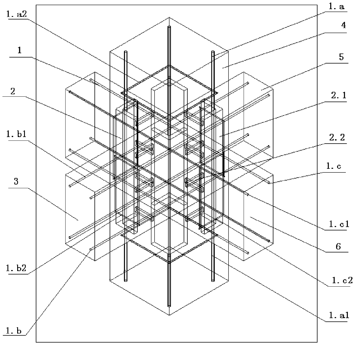
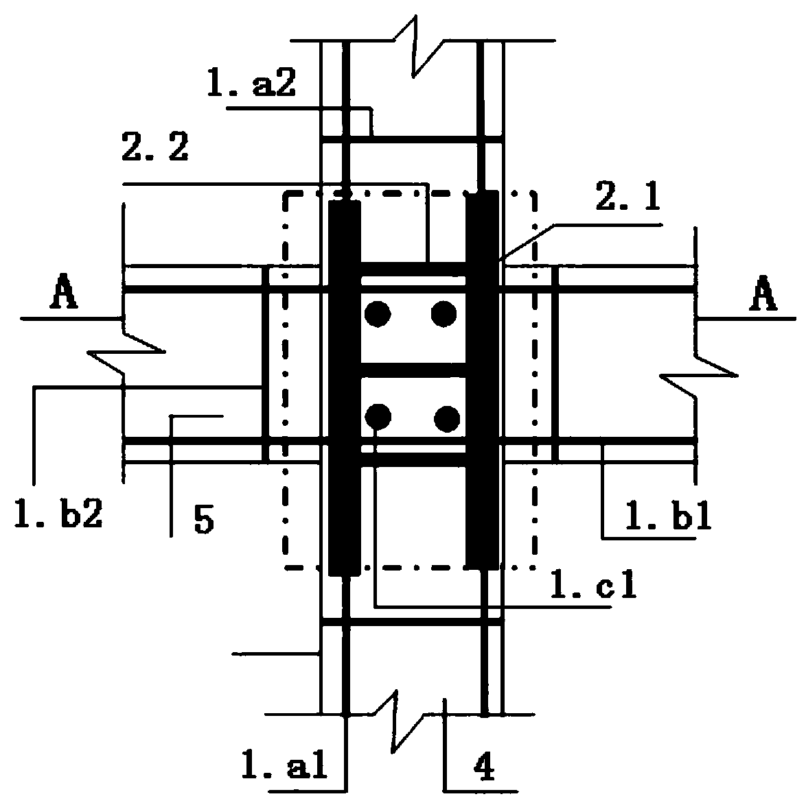
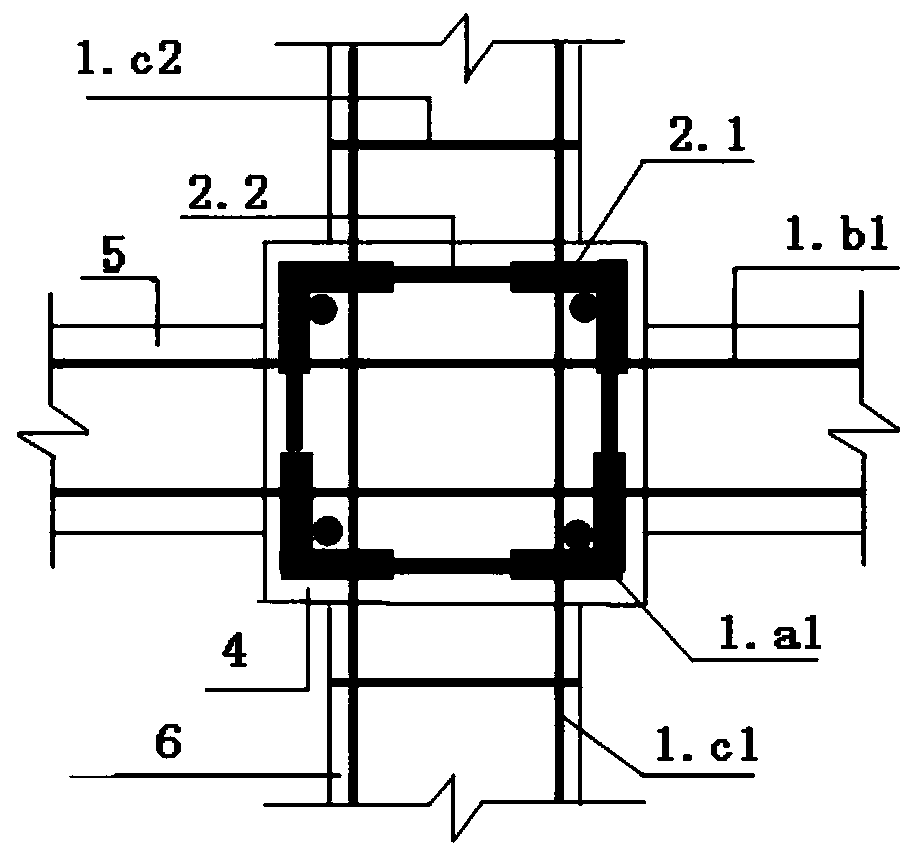
[0027] Such as Figure 1~3 As shown, a reinforced reinforced concrete frame node, which includes a reinforced skeleton 1 and a restrained steel skeleton 2, the reinforced skeleton 1 and the restrained steel skeleton 2 are poured with concrete 3 inside and outside, and the reinforced skeleton 1 includes a column reinforced skeleton 1. a. Crossbeam reinforcement skeleton 1.b and longitudinal beam reinforcement skeleton 1.c. The restraint steel skeleton 2 includes restraint steel 2.1 arranged vertically and symmetrically at the four corners of the column, and the restraint steel 2.1 is connected by welding with connecting panels 2.2;

[0028] Constrained profile steel 2.1 is constrained angle steel or constrained channel steel; wherein, constrained angle steel is four pieces of angle steel...


PUM


Abstract

The invention discloses an enhanced reinforced concrete frame joint. The enhanced reinforced concrete frame joint comprises a reinforced steel bar skeleton and a restraint steel skeleton, concrete ispoured in and out of the reinforced steel bar skeleton and the restraint steel skeleton. The restraint steel skeleton comprises restraint steel vertically and symmetrically arranged at the four corners of a column, and the restraint steel is connected through welding of connection batten plates or bolted connection. A columnar reinforced steel bar skeleton comprises columnar longitudinal ribs arranged on the four sides of the columnar section, and the columnar longitudinal ribs are arranged in the restraint steel skeleton. Cross beam reinforced steel bar skeleton comprises cross beam force bearing ribs, and a longitudinal beam reinforced steel bar skeleton comprises longitudinal beam force bearing ribs. The cross beam force bearing ribs and the longitudinal beam force bearing ribs are arranged in the restraint steel skeleton in an intersecting mode, and both penetrate through through-holes in the side walls of the restraint steel or the gaps among the restraint steel. By arranging therestraint steel skeleton in a joint area, the construction technology of the joint area is simplified, the phenomenon of dense stirrups in the joint area is avoided, dense pouring of concrete in the joint area is facilitated, the construction quality is ensured, and the anti-seismic properties such as bearing force and ductility of the joint core area are improved obviously.

Description

technical field [0001] The invention relates to the field of construction engineering, in particular to a reinforced reinforced concrete frame node. Background technique [0002] Reinforced concrete frame structures are widely used in the field of civil engineering in my country. The core area of ​​the joint is an extremely important hub of the frame structure and a key part of maintaining the integrity of the structure. my country is an earthquake-prone country. Under the action of earthquakes, the core area of ​​the joint becomes the weak part of the frame structure due to the complex action of bending moment, shear force and axial force. The core area of ​​the joint is often subjected to horizontal shear force several times that of the column, which is prone to shear brittle failure. Although the code for seismic design of buildings "GB50011-2010" stipulates the design principles of "strong shear and weak bending, strong columns and weak beams, strong nodes and weak comp...

Claims


Application Information

Patent Timeline
Patent Type & Authority Patents(China)
IPC IPC(8): E04B1/20E04B1/30E04B1/58
CPCE04B1/20E04B1/30E04B1/58
Inventor 颜燕祥李峻峰刘进军童友枝李晓目郭波
Owner HUBEI ENG UNIV
Why Eureka
Try Eureka