
Construction method of constructing beam-column joint using ring beam

A construction method and a technology of beam-column joints, applied in water conservancy projects, infrastructure engineering, construction, etc., can solve the problems of complex construction process of steel bar crossing and bad influence of joint structure

Inactive Publication Date: 2015-09-30
SHANGHAI NO 4 CONSTR
View PDF7 Cites 9 Cited by
  • Summary
  • Abstract
  • Description
  • Claims
  • Application Information

AI Technical Summary

Problems solved by technology

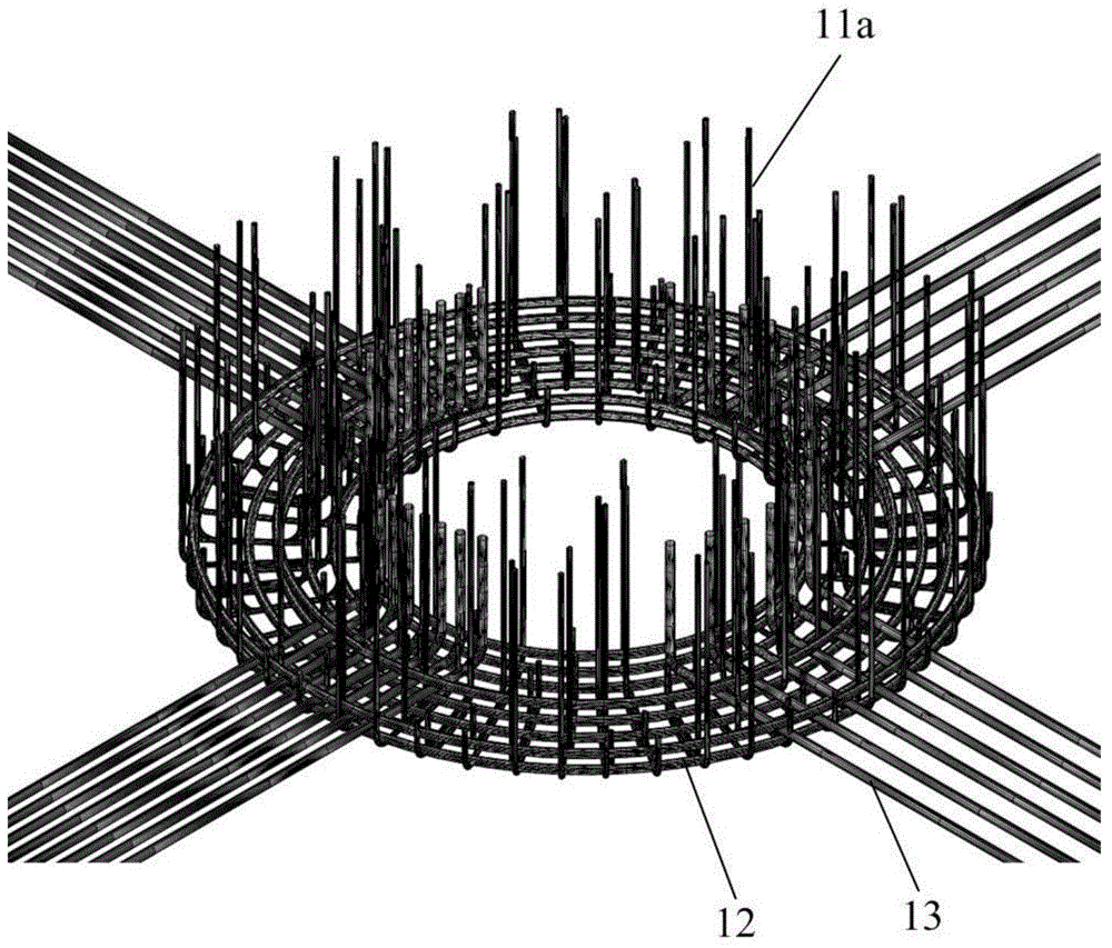
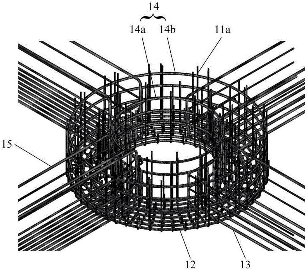
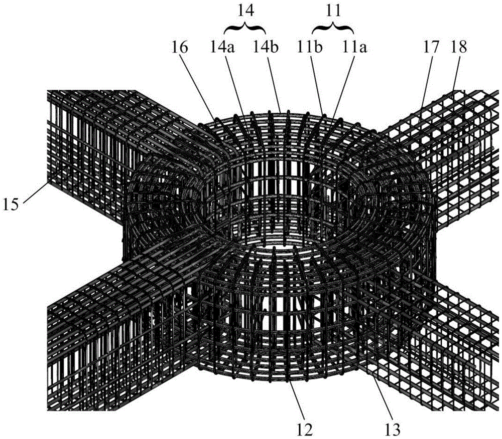
[0004] Aiming at the problem that the steel bar passing through the beam-column node position in the existing reverse method is complex, and the adjustment of the original steel bar structure on site has an adverse effect on the force of the node structure, the purpose of the present invention is to provide a construction method of using ring beams to construct beam-column nodes method, by setting ring beams to connect the steel bars in the CFST columns and the frame beams, erecting the ring beams and the steel bars in the frame beams in an orderly manner from bottom to top, which can not only avoid the crossing problem of the steel bars at the beam-column joints, but also improve the quality of the ring beams. And the shear bearing capacity of the steel tube concrete column improves the construction efficiency and ensures the construction quality of the beam-column joint structure

Method used


Image

  • Construction method of constructing beam-column joint using ring beam
  • Construction method of constructing beam-column joint using ring beam
  • Construction method of constructing beam-column joint using ring beam

Examples


Embodiment Construction

[0025] The construction method for constructing beam-column joints using ring beams proposed by the present invention will be further described in detail below in conjunction with the accompanying drawings and specific embodiments. Advantages and features of the present invention will be apparent from the following description and claims. The technical content and features of the present invention will be described in detail below by referring to the illustrated embodiments in conjunction with the accompanying drawings. It should be further noted that all the drawings are in very simplified form and use imprecise scales, and are only used to facilitate and clearly assist the purpose of illustrating the embodiments of the present invention. For the convenience of description, the "up" and "down" described below are consistent with the directions of up and down in the drawings, but this should not be a limitation of the technical solution of the present invention.

[0026] comb...


PUM


Abstract

The invention discloses a construction method of constructing a beam-column joint using a ring beam, and relates to the technical filed of building construction. The construction method aims at solving the problems that the construction technology of rebar traversing in the position of the joint of the beam-column joint is complicated in an existing reverse building method, and harmful effect is caused to the joint structure when adjusting an original rebar structure on site. The construction method comprises the steps that 1 construction is conducted to form a concrete filled steel tubular column in the reverse building method, and a ring beam bottom cast is fixed to a bent surrounding the concrete filled steel tubular column; 2 multiple first U-shaped stirrups, ring beam bottom bars and lower rebars are erected in radial direction supported by the ring beam bottom cast; 3 multiple ring beam waist bars and multiple frame beam waist rebars are erected in the longitudinal direction of the axis of the concrete filled steel tubular column; 4 ring beam far bars and second U-shaped stirrups are erected, the first U-shaped stirrups and the second U-shaped stirrups can be put together and erected to form first annular stirrups, and the first annular stirrups are enclosed and fixed to the outer sides of the ring beam bottom bars, the ring beam waist bars and the ring beam face bars; fixing side formworks are installed, concreting is conducted, when a designed strength is reached, the formworks are removed, and construction of the beam-column joint is completed.

Description

technical field [0001] The invention relates to the technical field of building construction, in particular to a construction method for constructing beam-column joints by using ring beams. Background technique [0002] At present, in the reverse method of foundation pit engineering, ring beams are used to connect the steel bars in the frame beams and concrete-filled steel tube columns. Shear connectors and X, Y direction frame beam main reinforcement and ring stirrups, etc. Therefore, the construction technology of the steel bars at the beam-column joints is particularly important. If there are mistakes in some links, the construction will not go smoothly. influences. [0003] Therefore, before the construction of the beam-column joint, how to optimize the construction steps so that the ring beam reinforcement and the frame beam reinforcement can be bound in an orderly manner, thereby ensuring the construction quality of the beam-column joint, is a technical problem to be...

Claims


Application Information

Patent Timeline
IPC IPC(8): E02D29/045E04B1/58E04B1/30
Inventor 孔德志陈梦然陈磊叶晟张铭陈建江
Owner SHANGHAI NO 4 CONSTR
Learn More