Steel tube concrete - steel support - concrete combined shear wall and manufacturing method thereof

A technology of steel tube concrete and combined shear walls, which is applied in the direction of walls, building components, and earthquake resistance. It can solve the problems of steel plate plane instability, improve bearing capacity, suppress out-of-plane instability, and change bearing capacity and stiffness attenuation. slow effect

Inactive Publication Date: 2009-05-20
BEIJING UNIV OF TECH
View PDF0 Cites 16 Cited by
  • Summary
  • Abstract
  • Description
  • Claims
  • Application Information

AI Technical Summary

Problems solved by technology

[0005] The technical problem to be solved by the present invention is to significantly improve the ductility and seismic energy dissipation capacity of the CFST frame shear wall, combining the advantages of the CFST frame shear wall and the steel plate shear wall, and setting steel supports on the steel plate In order to solve the problem of out-of-plane instability of steel plates, a composite shear wall of steel tube concrete-steel braces-steel plates was designed

Method used


Image

  • Steel tube concrete - steel support - concrete combined shear wall and manufacturing method thereof
  • Steel tube concrete - steel support - concrete combined shear wall and manufacturing method thereof
  • Steel tube concrete - steel support - concrete combined shear wall and manufacturing method thereof

Examples


Embodiment 1

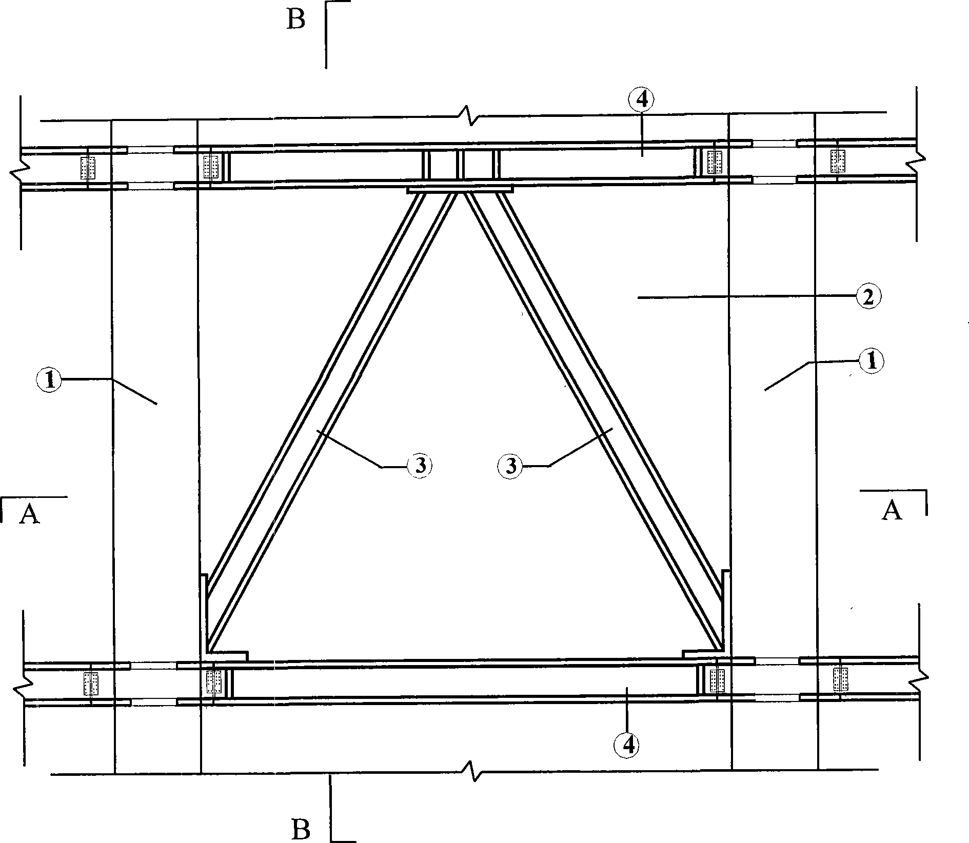
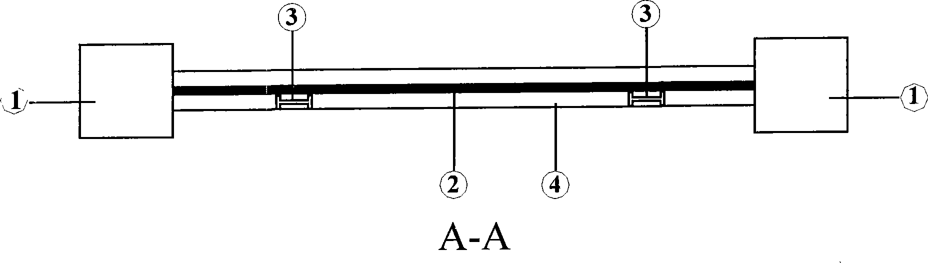
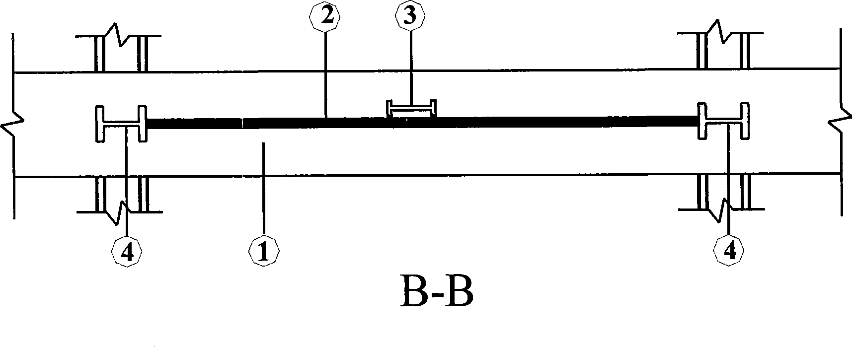
[0029] The structural diagram of a structural unit of the steel tube concrete-steel brace-steel composite shear wall is as follows figure 1 , figure 2 and image 3 shown. There is no reinforcement in the steel pipe concrete frame column 1; the frame beam of the shear wall is a steel beam 4; the steel brace 3 arranged on the steel plate 2 of the shear wall is herringbone. The upper end of the steel brace 3 is connected with the shaped steel beam 4 , and the lower right end of the steel brace 3 is connected with the frame column 1 of the steel tube concrete frame and the shaped steel beam 4 . Finally, the concrete-filled steel tube frame column 1 is poured and rammed into concrete to form a composite shear wall of concrete-filled steel tube-steel brace-steel plate.

[0030] Production Method:

[0031] 1) Fabricate the steel pipe concrete frame column 1, install a partition plate inside the steel pipe at the joint of the beam and column, weld a short steel beam outside the c...

Embodiment 2

[0037] The second structural form of CFST-steel braces-steel plate composite shear wall is as follows: Figure 4 As shown, X-shaped steel braces 3 are arranged on the steel plate 2 embedded in the shear wall. The steel braces 3 are arranged alternately on both sides of the steel plate. The lower end of the steel brace 3 is connected with the steel pipe concrete frame column 1 and the lower shaped steel beam 4 . Other aspects are the same as in Example 1.

Embodiment 3

[0039] The third structural form of steel tube concrete-steel brace-steel composite shear wall is as follows: Figure 5 As shown, the eight-shaped steel brace 3 is set on the shear wall steel plate, the upper end of the steel brace 3 is connected with the upper steel beam 4, and the lower end of the steel brace 3 is connected with the steel pipe concrete frame column 1 and the lower steel beam 4. Other aspects are the same as in Example 1.


PUM


Abstract

The invention discloses a steel pipe concrete-steep support-steel plate combine shear wall and making method thereof, belonging to the field of building construction. The steel pipe concrete-holed steel plate-concrete combine shear wall is characterized in that: the shear wall is composed of steel pipe concrete frame columns (1) and steel plate concrete shear wall boards, and the frame beam is provided with a section steel beam (3). A steel plate (2) embedded in the shear wall is provided with an opening, the two sides of the steel plate (2) are provided with steel bar nets composed of transverse steel bars (4) and longitudinal steel bars (5), and the steel bar nets at two sides of the steel plate (2) are tied by steel tie bars (7) at the opening on the steel plate (2). Compared with the conventional shear wall, the shear wall of the invention has large initial rigidity, high bearing ability, slow attenuation for bearing force and rigidity, good whole shock resistance and energy consumption performance, stable shock resistance performance, and reduced bottom shearing sliding destroy.

Description

technical field [0001] The invention relates to a steel tube concrete-steel brace-steel composite shear wall and a manufacturing method thereof, belonging to a shear wall and a manufacturing method thereof. Background technique [0002] In recent years, with the development of social production and the needs of people's lives, there are more and more large and complex high-rise buildings pursuing individualization, and the requirements for the seismic performance of the overall structure are also getting higher and higher. Reinforced concrete high-rise buildings with large quantities and wide areas are usually composed of beams, columns, floors, shear walls and cylinders. Shear walls and cylinders composed of shear walls are the core parts of high-rise building anti-seismic, so the shear wall structure The seismic performance of high-rise buildings plays a vital role in the safety and reliability of high-rise buildings. The existing reinforced concrete shear walls have poor...

Claims


Application Information

Patent Timeline
Patent Type & Authority Applications(China)
IPC IPC(8): E04B2/56E04B1/18E04B1/98
Inventor 曹万林杨亚彬张建伟董宏英张文江周中一
Owner BEIJING UNIV OF TECH
Why Eureka
Try Eureka