
Overall view visual system based on double-curve viewfinder

A panoramic vision and viewfinder technology, applied in the field of panoramic vision systems, can solve the problems of increasing system uncertainties, unfavorable system appearance, reducing system reliability, etc., and achieves convenient and simple replacement, low cost, and improved applicable space Effect

Inactive Publication Date: 2007-06-06
SHANGHAI JIAO TONG UNIV
View PDF0 Cites 18 Cited by
  • Summary
  • Abstract
  • Description
  • Claims
  • Application Information

AI Technical Summary

Problems solved by technology

However, the current products have certain defects in the design of the connection and installation of these three parts: one way is to use a completely fixed connection method for the three parts, that is, to install the viewfinder and the camera together in a one-time fixed way , such an approach results in limitations in the use of the panoramic vision product; another approach is to completely use movable connections for the three parts, such as bolted connections, so that the panoramic viewfinder, camera, etc. can be easily replaced, thereby increasing the The scope of use of the panoramic vision product, but such too many movable connections greatly reduce the reliability of the system, and it is easier to cause the bolts to loosen after long-term use, which increases the uncertainty of the use of the system, and is not conducive to the appearance of the system. Beautiful, not conducive to installation and portability

Method used


Image

  • Overall view visual system based on double-curve viewfinder
  • Overall view visual system based on double-curve viewfinder
  • Overall view visual system based on double-curve viewfinder

Examples


Embodiment Construction

[0015] The technical solution of the present invention will be further described below in conjunction with the accompanying drawings.

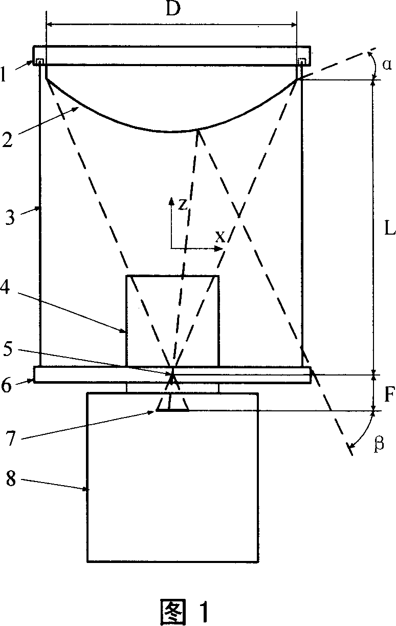
[0016] Fig. 1 is a structural schematic diagram of a panoramic vision system of the present invention. As shown in FIG. 1 , a panoramic viewfinder connector 1 is connected with a panoramic viewfinder 2 to form a panoramic viewfinder module. The zoom lens connector 6 is fixed to the zoom lens 4 through the threaded hole to form a zoom lens module. The upper part of the glass protective cover 3 is stuck in the groove of the outer ring of the panoramic view finder connector 1, and the lower part of the glass protective cover 3 is stuck in the groove of the outer ring of the zoom lens connector 6, so that the panoramic view finder 2 and the zoom lens 4 are Placed in the glass protective cover 3. The viewfinder camera 8 is connected to the zoom lens connector 6 through the bottom thread of the zoom lens connector 6 .

[0017] The camera sensor 7...


PUM


Abstract

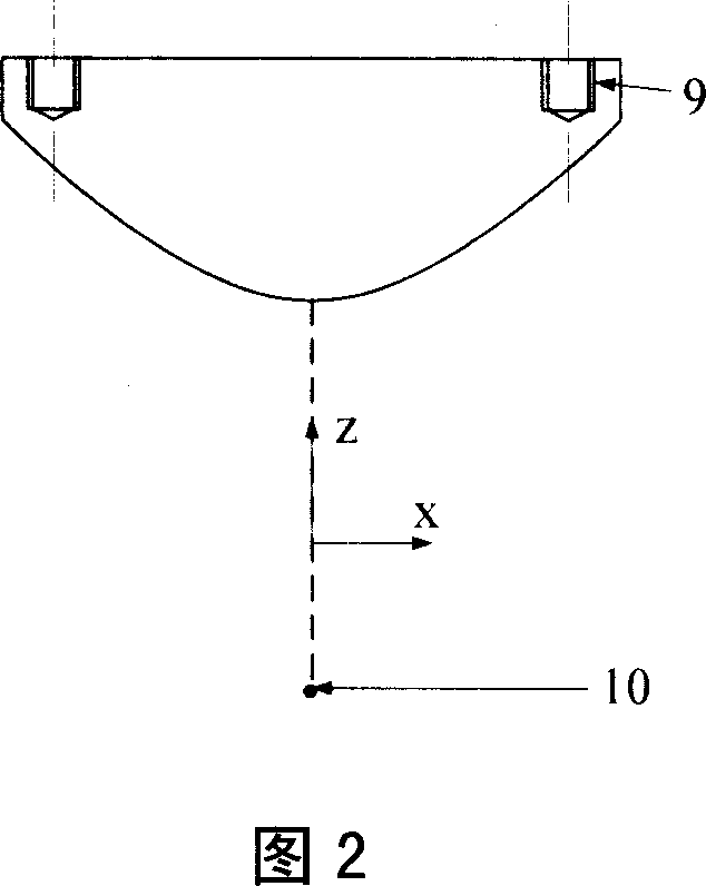
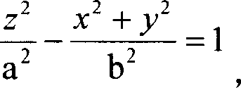
This invention relates to a kind of overall view vision system based on hyperboloid mirrorscope, overall view mirrorscope and overall view connector compose overall view finder module, the zoom lens connector and the zoom lens compose the zoom lens module, the upper part of the glass protecting cover is blocked in the flute of the overall view finder connector, the down part is blocked in the flute zoom lens connector, to make both the overall view mirrorscope and the zoom lens are put in the glass protecting cover, the finder telecamera links with the zoom lens connector. The centre of overall view mirrorscope , zoom lens and telecamera sensor are in the same straight line , it has ascertained optical imaging focal point of the overall view system; the said overall view mirrorscope is hyperboloid structure , the reflection focal which the hyperboloid point corresponded and the optical imaging focal point of the overall view system coincide. The overall view mirrorscope in the invention adopts the hyperboloid structure, it can satisfy the range demand of wide angles finder of the system, the module combination method is easy to assemble and change, has improved the reliability of the system.

Description

technical field [0001] The invention relates to a panoramic vision system based on a hyperboloid viewfinder, which integrates modules such as a hyperboloid viewfinder, a zoom lens, and a viewfinder camera, and uses technologies in optical imaging and mechanical design to improve the system's ability to identify and monitor the environment. breadth, precision and accuracy. Background technique [0002] Vision systems are very important sensing means in many fields, such as security, monitoring, robot systems, image processing, etc. For a long time, all units of industry, university and research institutes have continuously developed and improved their imaging systems according to different application occasions, in order to obtain images with more stable quality and more information. Panoramic vision system is gradually adopted by people because of its advantages of super large viewing angle. [0003] Panoramic vision technology is to use the principle of mirror reflection ...

Claims


Application Information

Patent Timeline
IPC IPC(8): G03B13/02G03B13/06G03B13/16G03B37/00H04N5/225
Inventor 王景川陈卫东
Owner SHANGHAI JIAO TONG UNIV
Learn More