Hybrid drawing cushion facility

A deep-drawing pad and electric drive technology, applied in the field of deep-drawing pad devices, can solve the problems of no structure space, large structure space, etc.

Inactive Publication Date: 2007-06-06
MASCHFAB MULLER WEINGARTEN AG
View PDF5 Cites 6 Cited by
  • Summary
  • Abstract
  • Description
  • Claims
  • Application Information

AI Technical Summary

Problems solved by technology

The disadvantage of the above-mentioned two electrically operated drawing pads is that they require a large installation sp

Method used


Image

  • Hybrid drawing cushion facility
  • Hybrid drawing cushion facility
  • Hybrid drawing cushion facility

Examples


Embodiment Construction

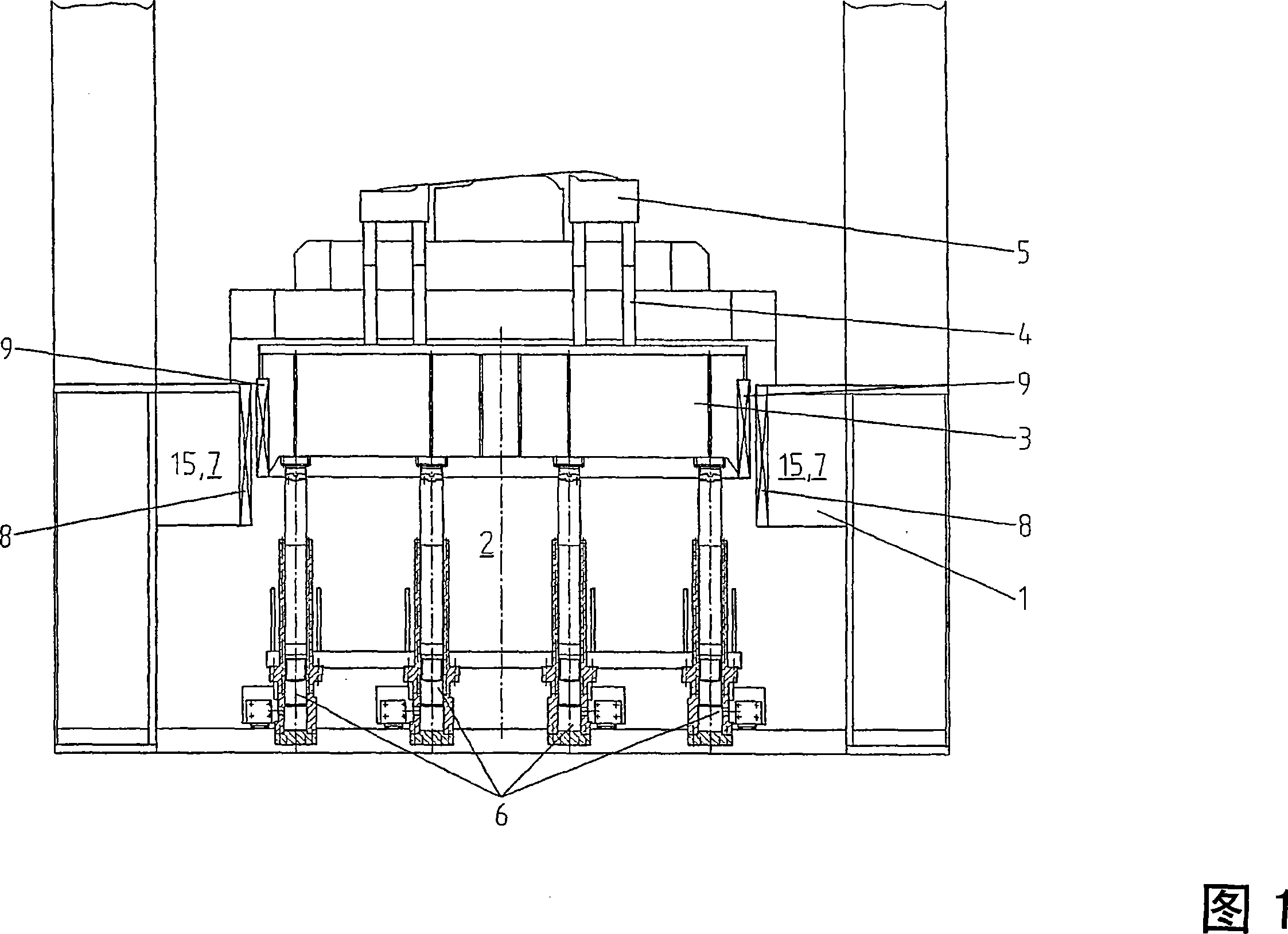
[0025] FIG. 1 shows a section of a press in a simplified illustration with a drawing pad arrangement 2 arranged in a press table 1 as a multipoint structure.

[0026] A pressure plate 3 guided longitudinally in the press table 1 is operatively connected via a pressure pin 4 to a sheet metal holder 5 of the lower tool. A fluid cylinder 6 is arranged between the press platen 3 and the press table 1 in order to generate the sheet holding force required for the deep-drawing process directed towards the upper die in the press ram, not shown. Here, the sectional illustration shows a first row of four fluid cylinders 6 of a total of eight-point drawing device. During the drawing phase of the sheet metal part, the pressing plate 3 is moved downward by the movement of the pressing rod, wherein the adjustment of the sheet holding force along the drawing stroke takes place by valve-controlled discharge of fluid out of the fluid cylinder 6 .

[0027] In order to generate the actively con...


PUM


Abstract

The invention relates to a hybrid drawing cushion facility which comprises a combination of fluid cylinders (6) and one or more electric drives (7, 15) acting upon the pressure box (3). The fluid cylinders (6) perform the force function on a high level and the electric drives (7, 15) perform the path function, such as pre-acceleration and run-up, and the force function on a low level when the fluid cylinders (6) are deactivated.

Description

technical field [0001] The invention relates to a drawing pad arrangement according to the preamble of claim 1 . Background technique [0002] Mechanical and hydraulic presses are forming process equipment for processing workpieces, especially thin sheet parts. For the forming of deep-drawn parts, the workpiece needs to be clamped in a specific way between the upper and lower dies of the press, wherein different forms of sheet-holding systems are known. From the magazine Bleche Rohre Profile (thin sheet tube profile), 39 (1992), pages 44 to 48, such deep drawing devices are known, which in part include complex systems with a controller in order to be able to transfer the sheet holding in a targeted manner. force. For deep-drawing presses, a distinction is made between so-called double-acting presses and single-acting presses, wherein, in double-acting presses, the sheet metal holder surrounding the press bar performs a leading movement relative to the press bar and the sub...

Claims


Application Information

Patent Timeline
IPC IPC(8): B21D24/02B21D24/10
CPCB21D24/10B21D24/02B21D22/20
Inventor 乌尔里希·弗兰克乌韦·达尔赖纳·赖兴巴赫托马斯·施皮斯霍弗格布哈特·恩格勒马库斯·米勒
Owner MASCHFAB MULLER WEINGARTEN AG
Why Eureka
Try Eureka