Rotary electric shaver

An electric shaver, rotary technology, applied in metal processing and other directions, can solve the problem of the entire electric shaver becoming larger, and achieve the effects of improving shaving experience, increasing the range of shaking angles, and increasing closeness

Inactive Publication Date: 2007-06-13
IZUMI PROD CO
View PDF1 Cites 8 Cited by
  • Summary
  • Abstract
  • Description
  • Claims
  • Application Information

AI Technical Summary

Problems solved by technology

Therefore, there is a problem that the blade portion installed on the upper portion of the main body portion becomes larger, and in particular, the entire electric shaver becomes larger when there are a plurality of outer blades.

Method used


Image

  • Rotary electric shaver
  • Rotary electric shaver
  • Rotary electric shaver

Examples


Embodiment Construction

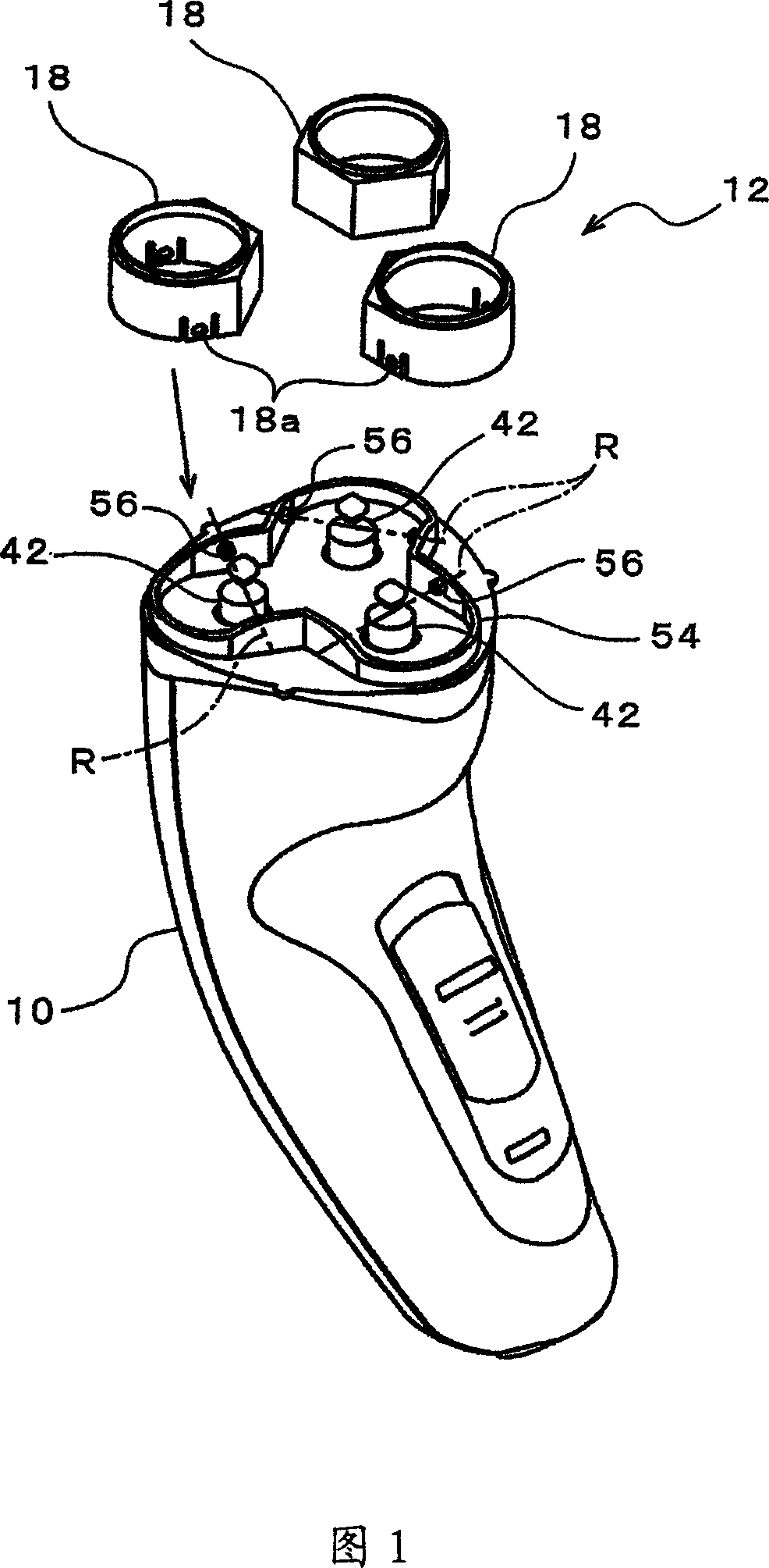
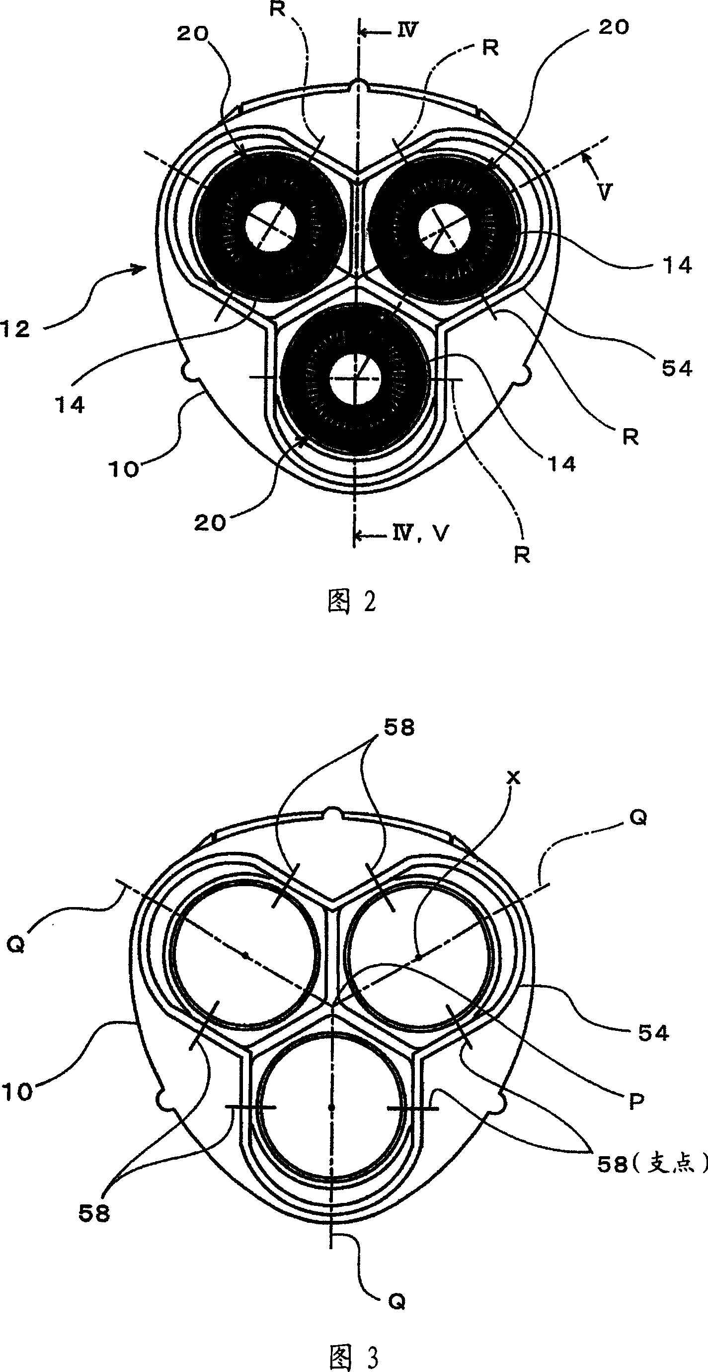
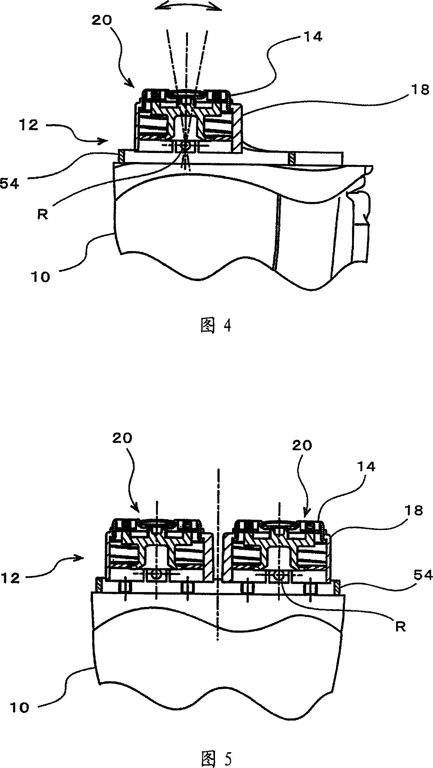
[0042] Fig. 1 is an exploded perspective view showing an embodiment of the present invention partially omitted, Fig. 2 is a top view of a cutting head portion, Fig. 3 is a top view showing a state in which an outer edge is removed from a cutting head portion, and Fig. 4 is a view according to IV of Fig. 2 - Sectional view of line IV, Fig. 5 is a sectional view according to line V-V in Fig. 2, Fig. 6 is an enlarged side sectional view of a blade unit along the rocking axis, Fig. 7 is a top view of a blade frame return spring, Fig. 8 is a top view according to A sectional view taken along line VIII-VIII of FIG. 7 . Moreover, FIG. 9 is an explanatory diagram of a state of use, and is a cutaway view at a position corresponding to the line V-V in FIG. 2 above.

[0043] In FIG. 1, reference numeral 10 is a main body part, and 12 is a blade part attached to this main body part. Three sets of blade units 20 formed of an outer blade 14 , an inner blade 16 described later, a blade fram...


PUM


Abstract

A rotary electric shaver including a plurality of substantially disc-shaped outer cutters, which are provided in the upper part of a shaver main body housing therein a motor, and inner cutters, which engage the outer cutters from below and are rotationally driven by the motor so as to cut hair entering into the hair introduction openings formed in the outer cutters; and in addition, substantially cylindrical cutter frames 18 for respectively holding the outer cutters in a depressible manner are provided so that cutter frames 18 can pivot in the upper surface of the shaver main body.

Description

technical field [0001] The present invention relates to a rotary electric shaver, in which an outer blade is held on the upper part of a main body provided with a motor, and the inner blade is rotated while elastically contacting the inner surface of the outer blade, thereby using the inner blade The blade cuts the hair that entered the hair introduction hole of the outer blade. Background technique [0002] In such electric shavers, it is known that the outer blade can be sunk in order to improve the closeness between the outer blade and the skin. That is, an outer blade mounting hole is formed in the outer blade frame fixed to the main body, and the outer blade is attached therefrom below, and the outer blade is elastically pushed upward. [0003] Usually, a compression coil spring is installed on the drive shaft that drives the inner blade in rotation, and the compression coil spring imparts upward recovery characteristics to the drive shaft, and the inner blade elastica...

Claims


Application Information

Patent Timeline
Patent Type & Authority Applications(China)
IPC IPC(8): B26B19/14B26B19/28B26B19/38
CPCB26B19/14B26B19/145
Inventor 冈部正树
Owner IZUMI PROD CO
Why Eureka
Try Eureka