
Detection method and apparatus for landing test

A technology of test device and clamping device, which is applied in the direction of measuring device, impact test, machine/structural component test, etc. It can solve problems such as vibration, affecting the accuracy of photography, and affecting the accuracy of landing detection, so as to achieve accurate detection results , Improve the effect of detection quality

Inactive Publication Date: 2007-06-13
陈 夏宗
View PDF1 Cites 46 Cited by
  • Summary
  • Abstract
  • Description
  • Claims
  • Application Information

AI Technical Summary

Problems solved by technology

[0004] However, because its clamp arm is limited to a specific test object, the impact angle measured after the test object is clamped is fixed, and the weight of the lower seat plus the lock ring of the weighted code makes its weight not the original test object's weight, thus making the impact Increased strength, resulting in G value is not as accurate as when only testing the test object
[0005] At the same time, there are other problems in the above-mentioned landing detection devices. First, although they all use the principle of free fall to detect the landing status of the product, in fact, the reason why the test object will fall is usually because of the collision or shaking of the external force. It will fall, so in fact, another gravitational acceleration force should be added to express the real state; secondly, because the traditional floor test machine has its camera installed on the collision plate, when the product falls and hits , usually produces vibration, which in turn affects the accuracy of photography, resulting in misjudgment of data, which seriously affects the accuracy of landing detection
[0006] From the above content, we can see that there are indeed many imperfections in the design of ordinary landing test devices, and it is impossible to effectively measure the actual landing status of the tested object, so the quality of the product cannot be really improved. Further improvement of the landing test device

Method used

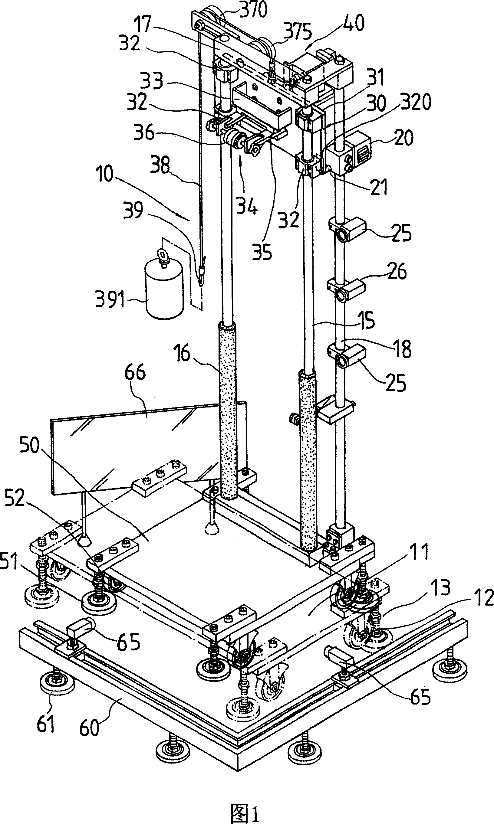
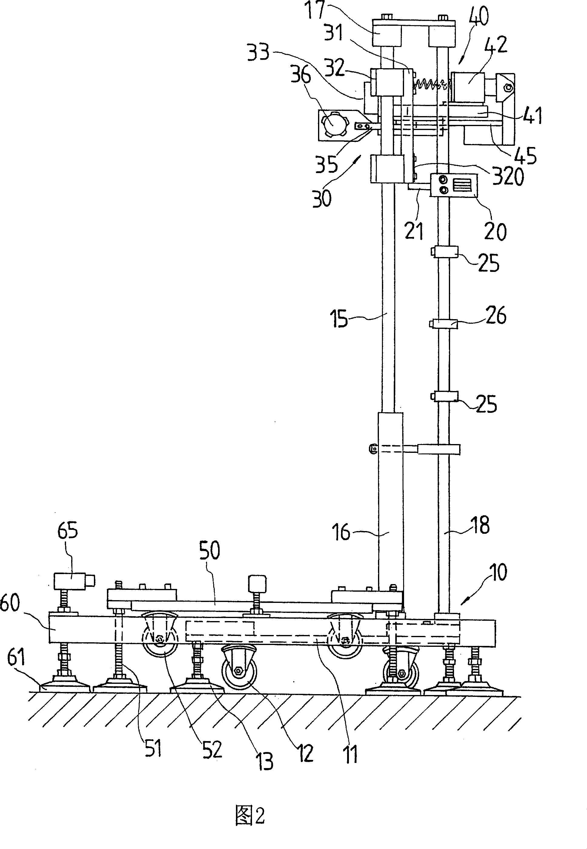
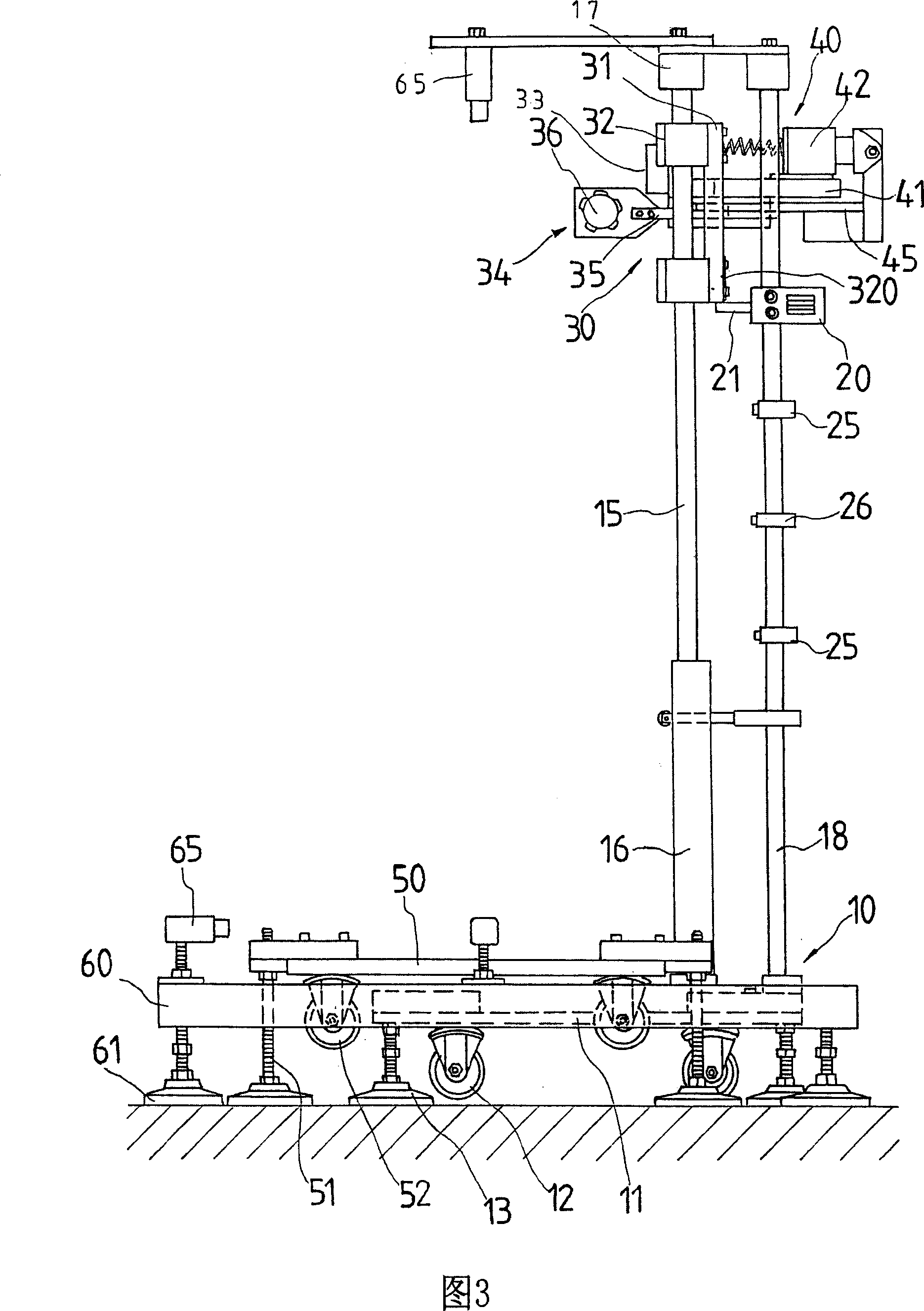

Image

  • Detection method and apparatus for landing test
  • Detection method and apparatus for landing test
  • Detection method and apparatus for landing test

Examples


Embodiment Construction

[0060] The present invention will be further described in detail below in conjunction with the accompanying drawings. It should be pointed out that the scope of protection required by the present invention is not limited to the specific forms of the following examples.

[0061] The present invention relates to a landing test device that can detect actual landing data and reduce interference. As shown in FIG. The seat 30 is provided with a clamping device 40 for clamping the test object 70. When the sliding seat 30 falls in a free fall relative to the frame 10 and releases the impact of the test object 70, the resistance of the test object 70 can be calculated. hit rate. The structure and action principle of the above-mentioned landing test device are the same as those of the existing devices, and are not the characteristics of the present invention, so they will not be described again.

[0062]As for the characteristic structure of the present invention, please refer to show...


PUM


Abstract

The invention discloses an experiment testing method and device to test stressed state of product when falling on the ground. It has a clamping device to hang the object, and a piezoelectricity sensing platform is set under it. A CCD camera is set outside the platform. Impact accelerometer is set on the testing point of the testing object. Using a monitoring program to start clamping device to drop the object in free falling state, recording the process until the object knocking at the piezoelectricity sensing platform trigger circuit, starting CCD camera to capture the process, calculating falling angle, taking simulation test, and comparing simulation G value and accelerometer testing G value, the accurate testing value would be gained. It would effectively improve economic benefit.

Description

technical field [0001] The invention belongs to the technical field of drop test devices, and in particular relates to a drop test detection method and a device thereof for detecting the force status of a product when it falls to the ground. Background technique [0002] The drop test is a method used to detect the force point and the load condition of the force point when the test object falls to the ground. The data obtained from the experiment can be used by the designer to modify the strength and shock absorption requirements of the entire product, so as to avoid the situation that the product will be easily broken due to collision when it is accidentally dropped, and it can also protect the components in the product shell to reduce unnecessary damage. Therefore, this type of landing detection device has a very wide range of applications, and there are many types. [0003] The floor testing machine mentioned in PCT patent WO 00 / 77487 is a fairly simple floor testing dev...

Claims


Application Information

Patent Timeline
IPC IPC(8): G01M7/08G01N3/303
Inventor 陈夏宗
Owner 陈 夏宗
Learn More