

LED luminescent device combined with rectifying circuit on secondary carrier and its production
A technology for light-emitting diodes and light-emitting devices, which is applied in the fields of circuits, semiconductor/solid-state device manufacturing, electrical components, etc., can solve the problems of complex manufacturing process and cannot save manufacturing time and cost, and achieves saving process time, circuit design, and reduction of cost effect
- Summary
- Abstract
- Description
- Claims
- Application Information
AI Technical Summary
Problems solved by technology
Method used
Image

Examples
Embodiment Construction
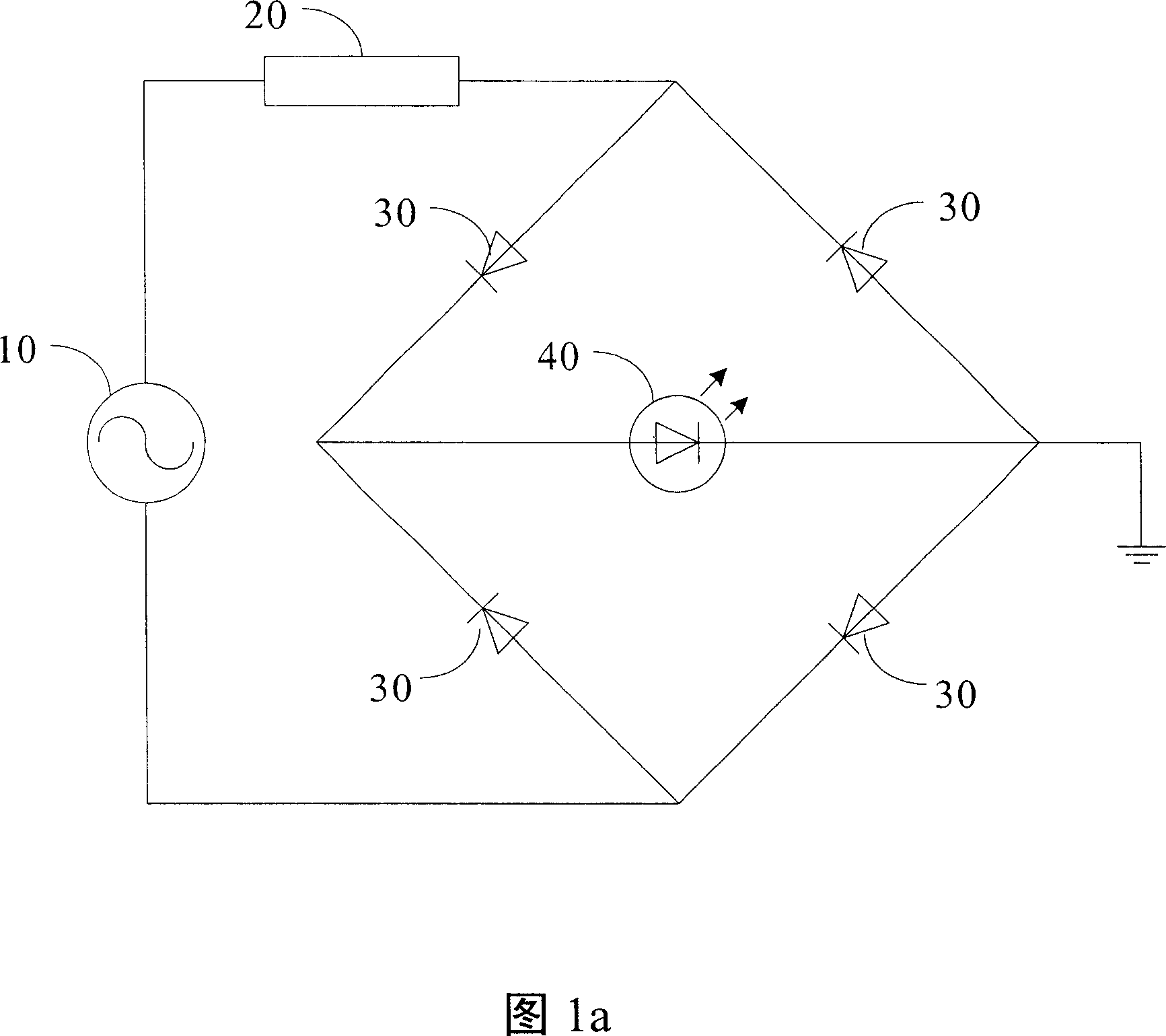
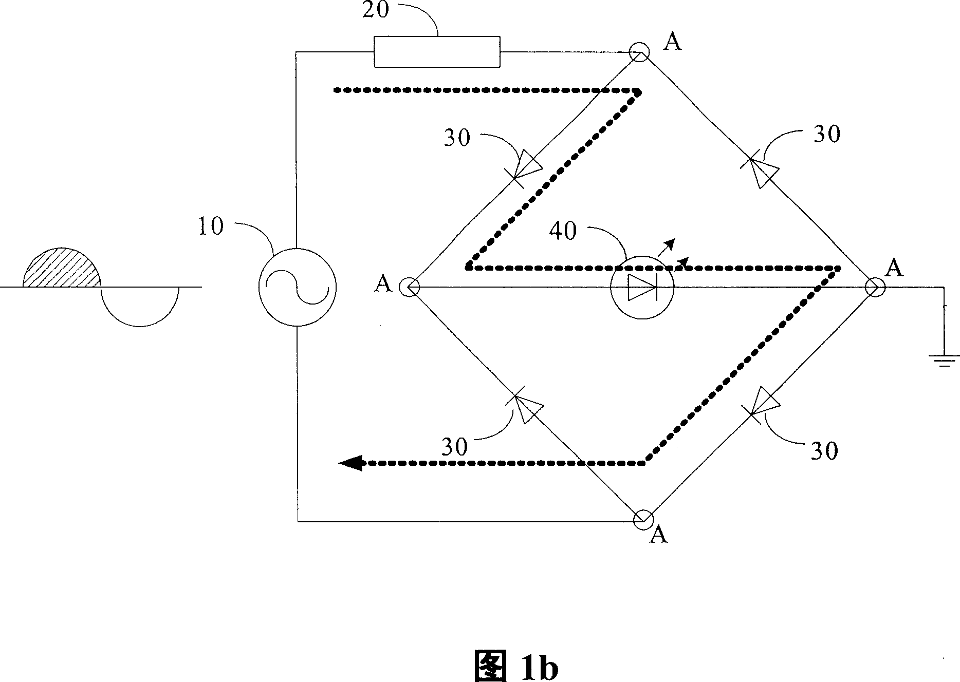
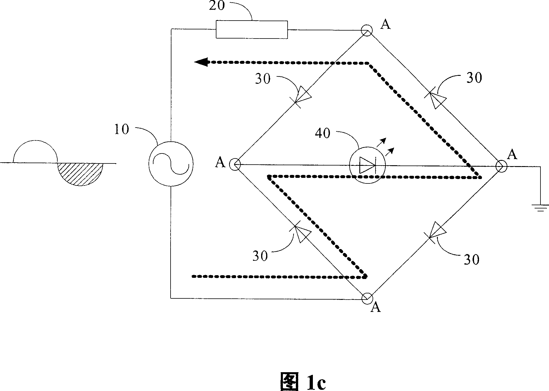
[0033] The invention proposes a light-emitting device which is directly driven by an alternating current and integrates a rectifier circuit and a light-emitting diode, and a related manufacturing method thereof. Please note that the rectification circuits integrated in the present invention include bridge rectification circuits, other full-wave rectification circuits, and half-wave rectification circuits. In other words, the present invention does not specifically limit the type of rectifier circuit, but for the convenience of description, the bridge rectifier circuit is mainly used as an example for illustration. In addition, the focus of the present invention is not on the integration of the rectifier circuit and the light-emitting diode load circuit as shown in Figure 1a. Such a circuit structure is already a known technology. The focus of the present invention is on the integrated circuit for realizing this circuit. architecture.
[0034] There are basically no special re...
PUM
 Abstract
Description
Claims
Application Information