Connector device for card

A technology of connectors and cards, which is applied to the parts of the connection device, connection, coupling device, etc., can solve the problems of shaking of the support shaft, misalignment of the second card, damage of the first protrusion 56c, etc., and achieve the effect of preventing reverse insertion

Inactive Publication Date: 2007-06-20
ALPS ALPINE CO LTD
View PDF1 Cites 5 Cited by
  • Summary
  • Abstract
  • Description
  • Claims
  • Application Information

AI Technical Summary

Problems solved by technology

[0015] However, in the conventional card connector device, the front end 52a of the second card 52 inserted from the insertion port 53a is repeatedly applied to the first positioning protrusion 56c of the engaging member 56, so the first protrusion 56c may be damaged.
In addition, there is a possibility that the position of the second card 52 to be inserted and mounted may be deviated due to vibration or the like occurring on the support shaft 56a supporting the engaging member 56 of the slide member 55.
[0016] In addition, in other embodiments, when the front end 52a of the second card 52 close to the left corner 52c abuts against the hook of the engaging lever, the engaging lever overcomes the pushing force of the torsion coil spring and pushes toward the retreating portion 55a. Side rotation, which may cause the second card installed in the second card installation part to be misaligned

Method used


Image

  • Connector device for card
  • Connector device for card
  • Connector device for card

Examples


Embodiment Construction

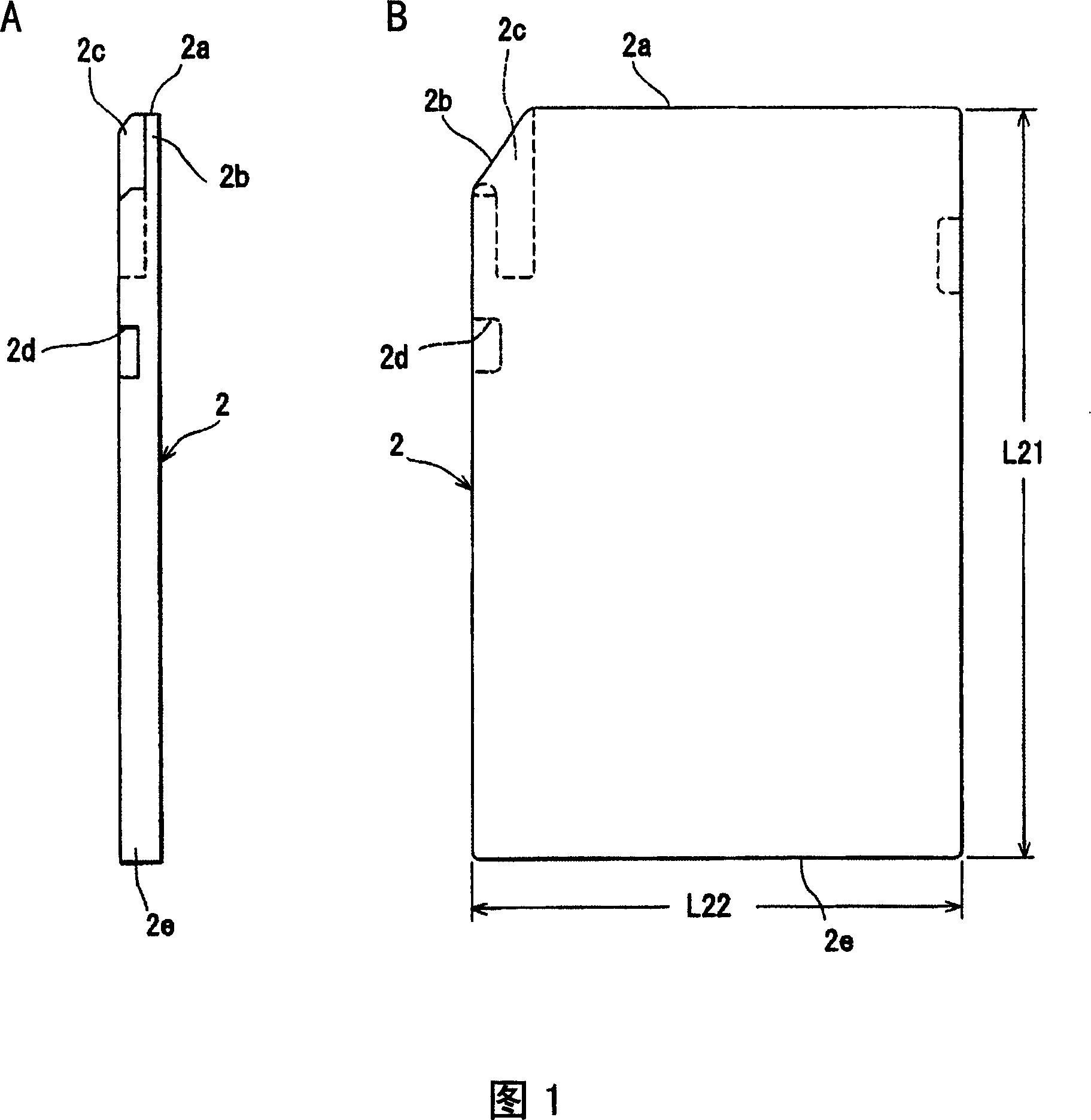
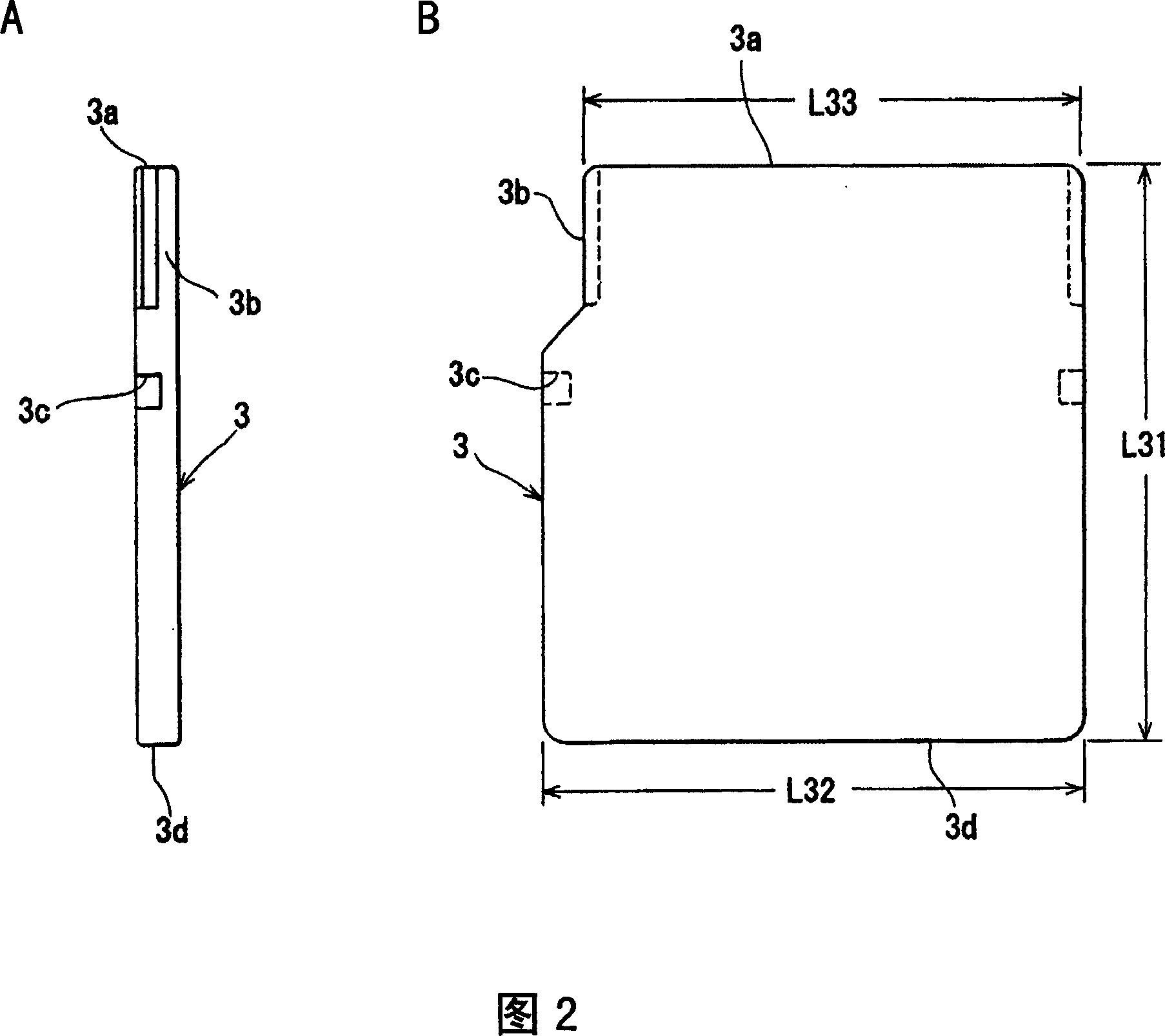
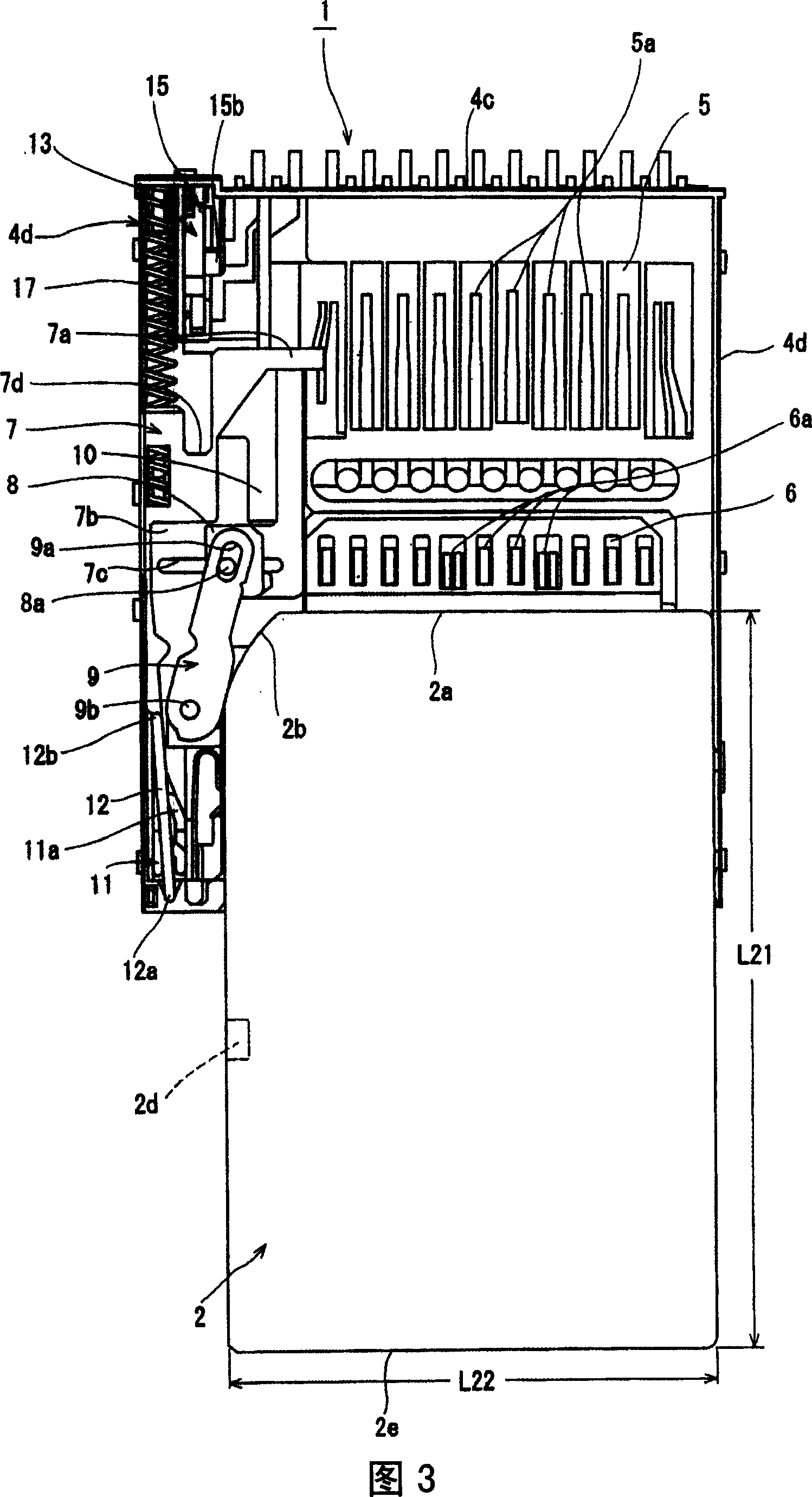
[0056] Hereinafter, one embodiment of the card connector device of the present invention will be described based on the drawings. Fig. 1 is a side view and a plan view illustrating the first card of the present invention, Fig. 2 is a side view and a plan view illustrating the second card of the present invention, and Figs. 3 and 4 are plan views illustrating the installation operation of the first card of the present invention 5, 6 is a plan view illustrating the installation operation of the second card of the present invention, FIG. 7 is a plan view when the sliding member is in the initial state in the card connector device of the present invention, and FIG. 8 is 2-- 2 is a cross-sectional view, FIG. 9 is a top view of the sliding member in the card device of the present invention, FIG. 10 is a cross-sectional view of 4-4 in FIG. 9, and FIG. 11 is a diagram illustrating the sliding member and the stop member of the present invention, FIG. 12 is a diagram illustrating the stop m...


PUM


Abstract

The present invention provides a card connector device, which can reliably fit the second card to the card fitting part without to wrong position even insert the second card to the cart fitting part again and again. The case of the card connector device (1) of the present invention formed with card inserting path for sliding the first or second card (2, 3) when inserting them to the first or second card fitting part (5, 6), the spacing component (8) is supported by the sliding component (7) and can slide in the orthogonal direction to the inserting direction of the first or second card. The spacing component (8) can retreat to the retreating part (7b) departing from the card inserting path when fitting the first card (2) to the first card fitting part (5). The spacing component (8) lies inthe inserting path when fitting the second card (3) to the second card fitting part (6), the front part (3a) of the second card that inserted to the card inserting path is abutting to the spacing component.

Description

Technical field [0001] The present invention relates to a connector device for a card, and more particularly to a connector device for a card capable of mounting different types of cards in predetermined card mounting portions. Background technique [0002] For example, the content described in Patent Document 1 is used to describe a conventional card connector device. The conventional card connector device, as shown in FIGS. 14 to 16, is provided with a first card 51 that can be inserted and installed from the insertion port 53a. , And the outer shell 53 of the second card 52 that is shorter in length than the first card 51. [0003] Inside the housing 53, the sliding member 55 pushed in the ejection direction by the urging force of the compression spring 54 is arranged so as to be located at the initial position shown in FIG. 14. [0004] The sliding member 55 is provided with a vertically long engaging member 56, and a support shaft 56 a formed on one side of the engaging memb...

Claims


Application Information

Patent Timeline
Patent Type & Authority Applications(China)
IPC IPC(8): H01R12/16H01R13/629H01R13/631H01R27/00G06K17/00
Inventor 村山丈刚
Owner ALPS ALPINE CO LTD
Why Eureka
Try Eureka