
Data transmission in a communication network

A technology of data transmission and communication network, which is applied in the field of communication network and can solve the problem of not being

Inactive Publication Date: 2007-06-20
KONINKLIJKE PHILIPS ELECTRONICS NV
View PDF0 Cites 3 Cited by
  • Summary
  • Abstract
  • Description
  • Claims
  • Application Information

AI Technical Summary

Problems solved by technology

It shows that this is not a very flexible approach

Method used

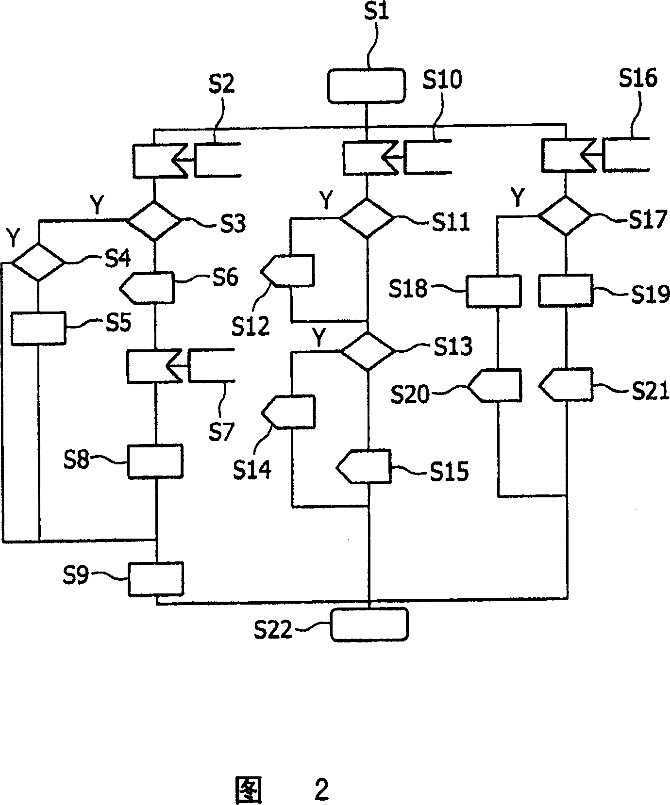
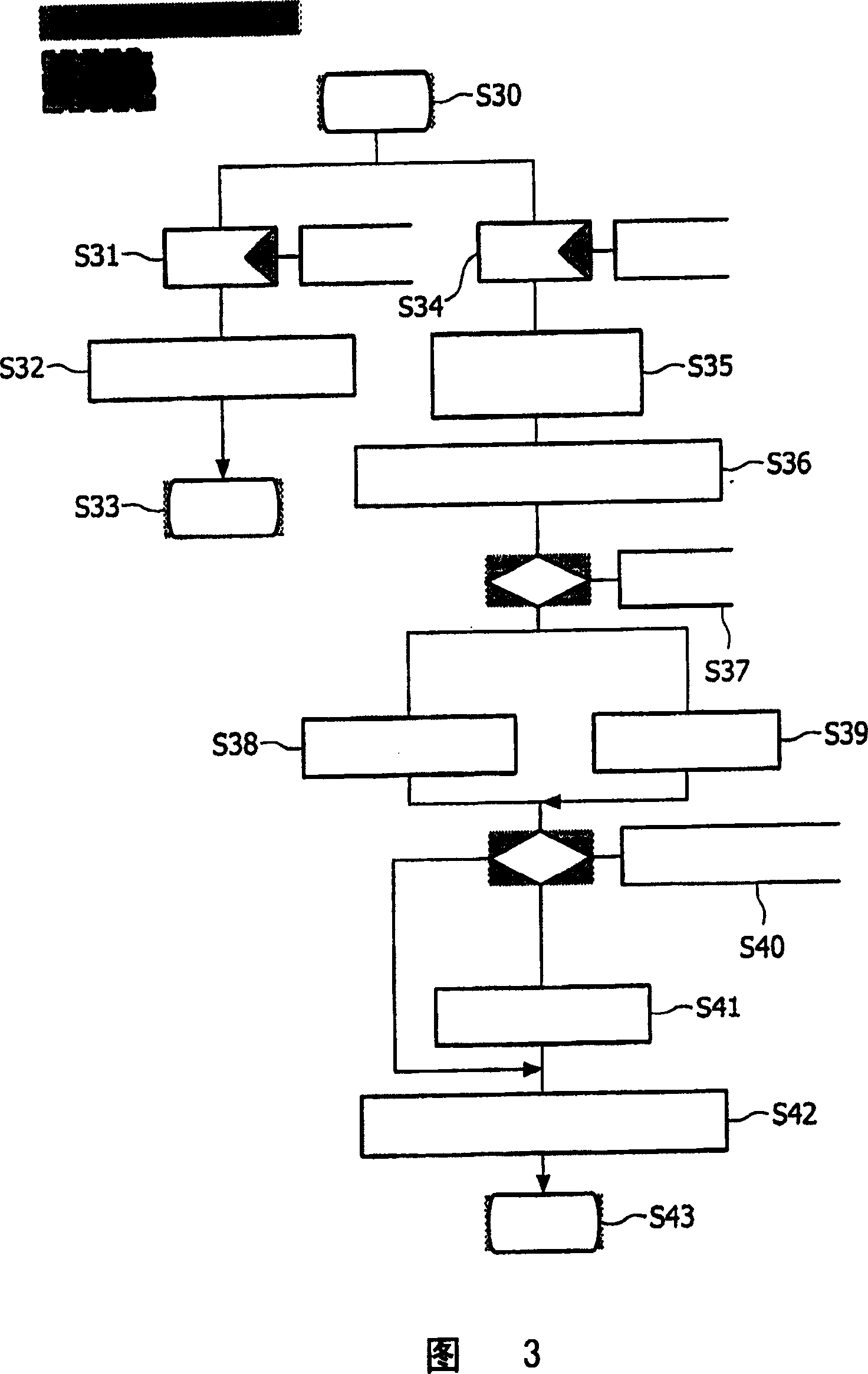

Image

  • Data transmission in a communication network
  • Data transmission in a communication network
  • Data transmission in a communication network

Examples


Embodiment Construction

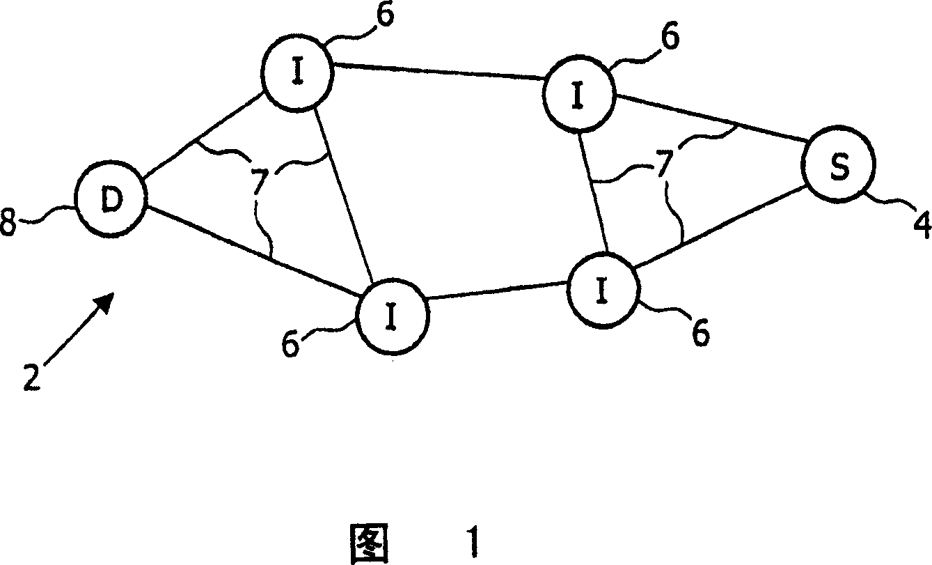
[0040] Fig. 1 shows a schematic diagram of a typical communication network 2 comprising network nodes 4, 6, 8 according to the invention. The figure shows three types of network nodes. The type of network node is determined by its role in the network. A source network node 4 (indicated by the letter S) is, for example, a network node which has to send information in the form of data packets to a destination network node 5 . The destination network node 8 is a second type of network node (indicated by the letter D). It is the receiver of the message. A third type of network node as depicted in FIG. 1 is an intermediate network node 6 and it is denoted by the letter I in FIG. 1 . It is responsible for relaying any messages sent from source network node 4 to destination network node 8 . The communication network 2 in Fig. 1 represents a wireless network. The structure of the network is based on self-organization. That means that the network nodes 4, 6, 8 do not depend on an...


PUM


Abstract

A mobile ad hoc network describes an ad hoc network in which each connection point or network node changes its position dynamically. Such a network is known for rapid changes of the network topology whereas each node is able to join and leave the network dynamically and often without warning. These dynamic changes can lead to the degrading of the stability of links between the network nodes. According to the present invention, a method is provided to smoothly replace degrading links with stable ones. Advantageously, this results in higher network stability and offers a high flexibility for routes in a dynamically changing network.

Description

technical field [0001] The invention relates to the field of communication networks and to routing protocols. In particular, the present invention relates to a method for transmitting data in a communication network, to the corresponding network and its components. Background technique [0002] Except for fixed networks, connections between network nodes in wireless networks are not done by fixed lines. Wireless networks use the air to connect two or more peers to each other. Links are wireless channels and thus path quality may vary. Negative influences such as interference, reflections, attenuation caused by the distance between communication partners have an influence on the quality of the link in addition to the bandwidth limitation. And the worse the link quality, the lower the available bandwidth corresponding to the available rate. Therefore stable links may degrade with communication device differences. [0003] In the development of next-generation wireless net...

Claims


Application Information

Patent Timeline
IPC IPC(8): H04L12/56
CPCH04W40/02H04W40/00H04W40/12H04W24/00H04W84/18H04L45/00H04W40/16H04L45/22
Inventor F·达尔马塞斯M·-L·鲍
Owner KONINKLIJKE PHILIPS ELECTRONICS NV
Learn More