

Electronic turning warning squealer-flash for automobile
A technology for automotive electronics and flashers, which is applied in the directions of sound signal devices, optical signals, vehicle components, etc., can solve the problems of easy sparks and low reliability of flashers.
- Summary
- Abstract
- Description
- Claims
- Application Information
AI Technical Summary
Problems solved by technology
Method used
Image

Examples
specific Embodiment approach 1
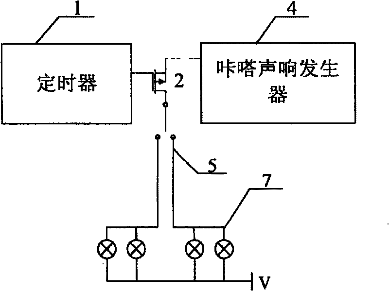
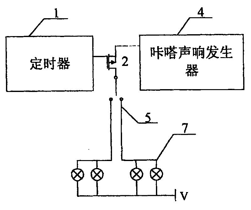
[0007] Specific implementation mode one: the following combination figure 1 with figure 2 Describe this embodiment in detail, this embodiment is made up of timer 1, VMOS tube switch 2, click sound generator 4, steering switch 5 and display lamp group 7, the output terminal of described timer 1 is connected the gate of VMOS tube switch 2 The source of the VMOS tube switch 2 is connected to the moving end contact of the steering switch 5, the drain of the VMOS tube switch 2 is connected to the input end of the click generator 4, and the static end contact of the steering switch 5 is connected to the display lamp group 7 One end of the display lamp group 7 is connected to the power supply V. After power on, the timer generates a timing signal to drive the VMOS tube switch at regular intervals, and the VMOS tube switch controls the flickering of the lamp. At the same time, the click sound generator generates the frequency of the analog relay sound, so that the buzzer emits the c...
specific Embodiment approach 2
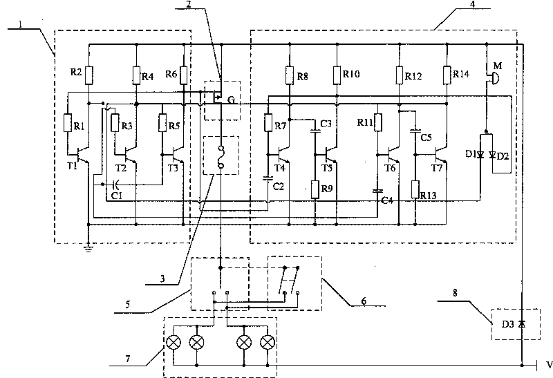
[0008] Specific implementation mode two: the following combination figure 2 Describe this embodiment in detail. The difference between this embodiment and the first embodiment is that the timer 1 is composed of a first resistor R1, a second resistor R2, a third resistor R3, a fourth resistor R4, a fifth resistor R5, and a sixth resistor. R6, the first capacitor C1, the first transistor T1, the second transistor T2 and the third transistor T3, one end of the first resistor R1 is connected to the base of the first transistor T1, and the other end of the first resistor R1 is connected to the sixth One end of the resistor R6, the collector of the third transistor T3 and the gate of the VMOS switch 2, the collector of the first transistor T1 are connected to one end of the second resistor R2, one end of the third resistor R3 and one end of the first capacitor C1, The emitter of the first transistor T1 is connected to the ground, the other end of the second resistor R2 is connected...
specific Embodiment approach 3
[0009] Specific implementation mode three: the following combination figure 2 This embodiment is described in detail. The difference between this embodiment and the second embodiment is that the click sound generator 4 is composed of the seventh resistor R7, the eighth resistor R8, the ninth resistor R9, the tenth resistor R10, the eleventh resistor R11, The twelfth resistor R12, the thirteenth resistor R13, the fourteenth resistor R14, the second capacitor C2, the third capacitor C3, the fourth capacitor C4, the fifth capacitor C5, the fourth transistor T4, the fifth transistor T5, the sixth Transistor T6, the seventh transistor T7, the first diode D1, the second diode D2 and the buzzer M, one end of the second capacitor C2 is connected to the gate of the VMOS transistor switch 2, and the second capacitor C2 The other end of the seventh resistor R7 is connected to one end of the seventh resistor R7 and the base of the fourth transistor T4, and the other end of the seventh re...
PUM
 Abstract
Description
Claims
Application Information