High-power TE-TEM microwave mode converter

A technology of TE-TEM and mode converter, which is applied in the direction of waveguide devices, electrical components, circuits, etc., can solve the problems of insufficient power capacity and difficulty in manufacturing, etc., to achieve improved power capacity, good conductivity, not easy to break or deformation effect

Pending Publication Date: 2020-09-18
四川三三零半导体有限公司
View PDF0 Cites 0 Cited by
  • Summary
  • Abstract
  • Description
  • Claims
  • Application Information

AI Technical Summary

Problems solved by technology

[0006] Based on the above problems, the object of the present invention is to provide a high-power TE-TEM microwave mode converter, which is used to solve the problems of insufficient power capacity and difficult manufacture of TE-TEM mode converters in the prior art

Method used


Image

  • High-power TE-TEM microwave mode converter
  • High-power TE-TEM microwave mode converter
  • High-power TE-TEM microwave mode converter

Examples


Embodiment 1

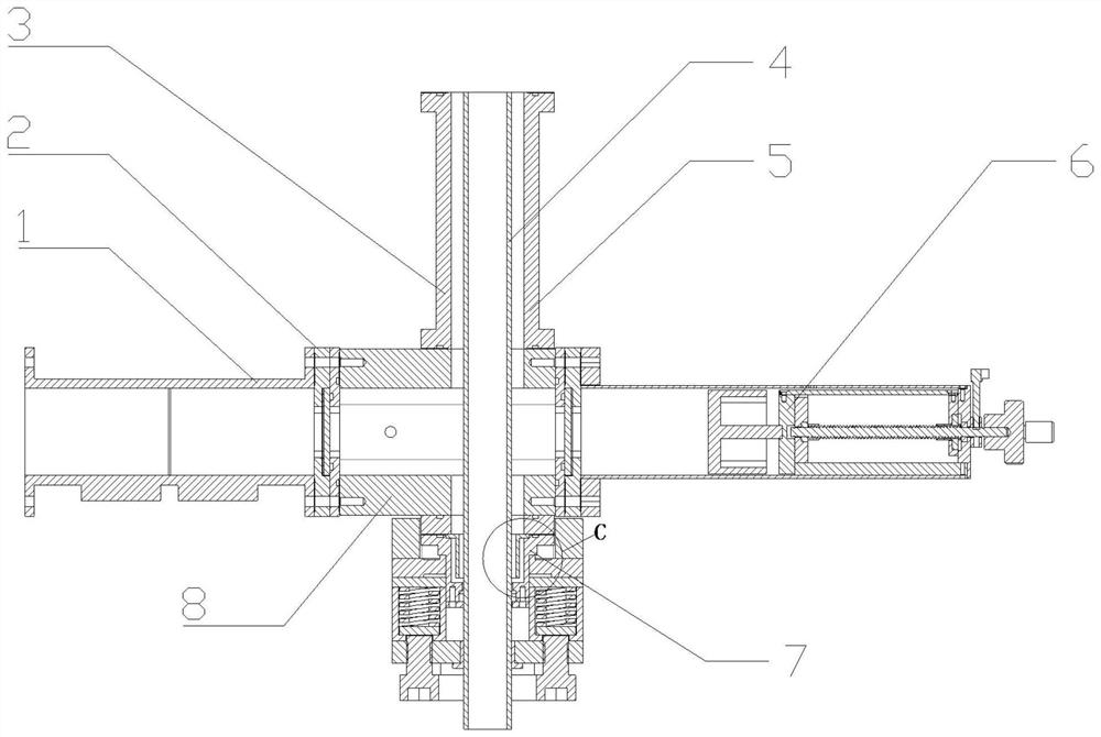
[0035] Such as figure 1 with 9 As shown, a high-power TE-TEM microwave mode converter includes a central waveguide 8, the left end of the central waveguide 8 is connected with a microwave feeding waveguide 1, the right end is connected with a microwave sliding circuit breaker 6, and the upper end is connected with a coaxial output 3, The lower end is connected with a coaxial short-circuit surface 7, and the coaxial output 3 is provided with a coaxial inner conductor 4 passing through the central waveguide 8 and the coaxial short-circuit surface 7 in sequence, and the coaxial short-circuit surface 7 includes a A centering ring 71, a short-circuit out-of-plane conductor 73 is installed on the centering ring 71, a coaxial down extension 74 is installed between the short-circuit out-of-plane conductor 73 and the center waveguide 8, and a coaxial down-extension section 74 and the short-circuit out-of-plane conductor 73 A microwave choke coil 72 which is not in contact with the coa...

Embodiment 2

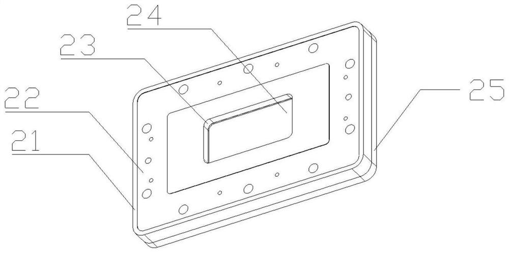
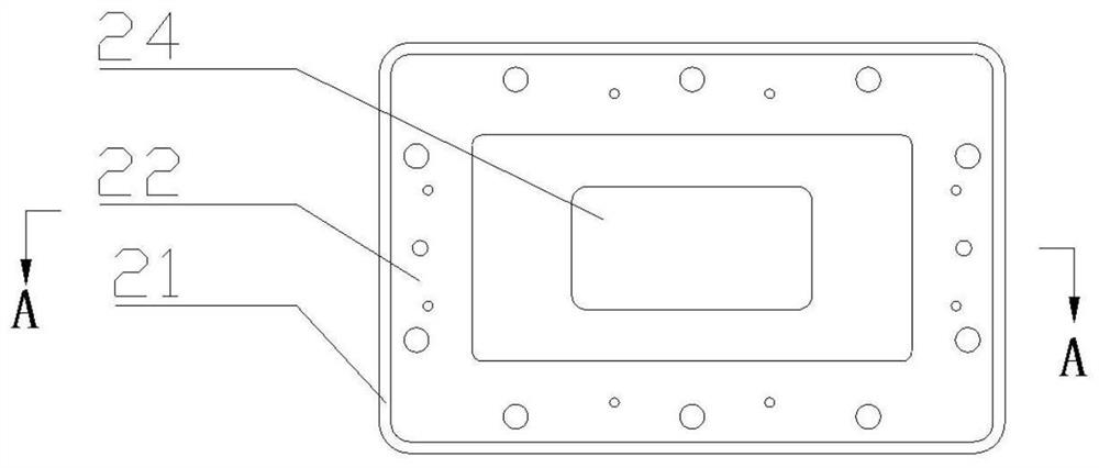
[0042] Such as Figure 2-5 As shown, on the basis of the above-mentioned embodiment 1, this embodiment provides the specific structure of the sealing window 2 and the microwave sliding circuit breaker 6, that is, the sealing window 2 includes an upper flange 21 and a lower flange 25 connected to each other, and the upper flange 21 and the lower flange 25 are connected to each other. The middle part of the flange 21 and the lower flange 25 has a window 27, and the bottom surface of the upper flange 21 has a mounting groove 29, and the gasket 26 and the quartz glass plate 24 in contact with each other are installed in the mounting groove 29 in sequence from top to bottom. , the quartz glass sheet 24 can close the window 27, and there is also a sealing groove 28 between the lower flange 25 and the quartz glass sheet 24, a sealing ring is installed in the sealing groove 28, the top surface of the upper flange 21 and the bottom surface of the lower flange 25 Both are provided with ...


PUM


Abstract

The invention relates to the technical field of microwave mode converters, and in particular relates to a high-power TE-TEM microwave mode converter which is used for solving the problems of insufficient power capacity and high manufacturing difficulty of a TE-TEM mode converter in the prior art. The high-power TE-TEM microwave mode converter comprises a central waveguide, a microwave feed-in waveguide, a microwave sliding circuit breaker, a coaxial output, a coaxial short-circuit surface and a coaxial inner conductor; the coaxial short-circuit surface comprises a centering ring installed in the coaxial inner conductor; a short-circuit surface outer conductor is installed on the centering ring; a coaxial downward-extending section is installed between the short-circuit surface outer conductor and the central waveguide; and a microwave choking coil which is not in contact with the coaxial inner conductor is installed between the coaxial downward-extending section and the short-circuit surface outer conductor. The coaxial downward extending section, the short-circuit surface outer conductor and the end face of the microwave choking coil are in contact, the electric conductivity is good, the sparking phenomenon is avoided, the power capacity of the converter can be improved, meanwhile, the converter can be divided into a plurality of parts during machining, and therefore the manufacturing difficulty is greatly reduced.

Description

technical field [0001] The invention relates to the technical field of microwave mode converters, in particular to a high-power TE-TEM microwave mode converter. Background technique [0002] In many high-power microwave applications, it is necessary to convert the TE10 mode microwave in the rectangular waveguide to the TEM mode in the coaxial waveguide. The TE-TEM mode converters in the prior art are mainly divided into two types: antenna type and button type. . [0003] The antenna-type mode converter needs to use a dielectric coaxial waveguide. The coaxial inner conductor and antenna are fixed by the dielectric in the coaxial waveguide. The dielectric loss is high, the power capacity is small, and the inner conductor cannot be installed firmly, so it cannot be used for high-power and Occasions where force-bearing installation is required. [0004] The door-button mode converter needs to set a cylindrical or tapered step in the rectangular waveguide, which requires comple...

Claims


Application Information

Patent Timeline
Patent Type & Authority Applications(China)
IPC IPC(8): H01P1/16
CPCH01P1/16
Inventor 袁博刘虎陈实
Owner 四川三三零半导体有限公司
Why Eureka
Try Eureka