A kind of installation method of power taking structure

An installation method and electronic technology, applied in the direction of electrode structure, electrostatic separation, power supply technology, etc., can solve the problems of reducing work efficiency, poor contact, unreliable contact, etc., and achieve the effect of improving work efficiency and preventing harm

Inactive Publication Date: 2015-08-26
ANHUI BINKEN ELECTRICAL CO LTD
View PDF5 Cites 0 Cited by
  • Summary
  • Abstract
  • Description
  • Claims
  • Application Information

AI Technical Summary

Problems solved by technology

[0005] However, in the prior art, the electric precipitator in the air purifier adopts the following method: the connection method between the electronic precipitator and the power supply is a point contact method, and its contact is unreliable. During transportation or installation, it is easy to Make the contact point loose, resulting in poor contact, which will cause ignition during use and cause certain hazards; moreover, this connection method is very troublesome during installation and disassembly. When installing, you need to install the electronic dust collector first. Finally, connect the power cord. When disassembling, you need to disconnect the power cord first, and then disassemble the electronic dust collector, which takes time and effort and reduces work efficiency.

Method used


Image

  • A kind of installation method of power taking structure
  • A kind of installation method of power taking structure
  • A kind of installation method of power taking structure

Examples


Embodiment Construction

[0027] In order to make the objectives, technical solutions, and advantages of the present invention clearer, the following further describes the present invention in detail with reference to the accompanying drawings and embodiments. It should be understood that the specific embodiments described herein are only used to explain the present invention, but not to limit the present invention.

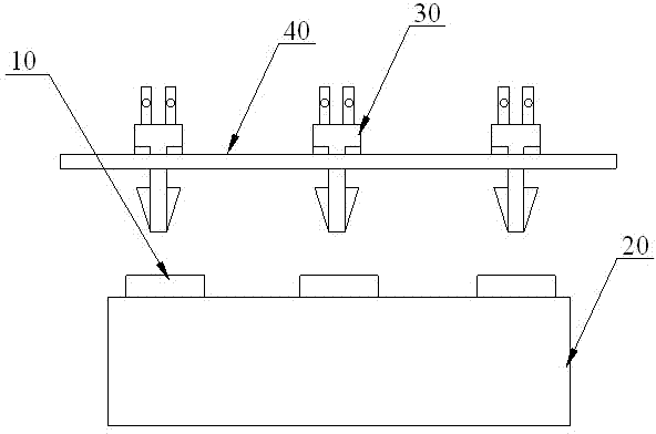
[0028] See image 3 , image 3 It is a schematic diagram of the structure of the electrode plate, electrode sheet, connected electric plate and electronic dust collector.

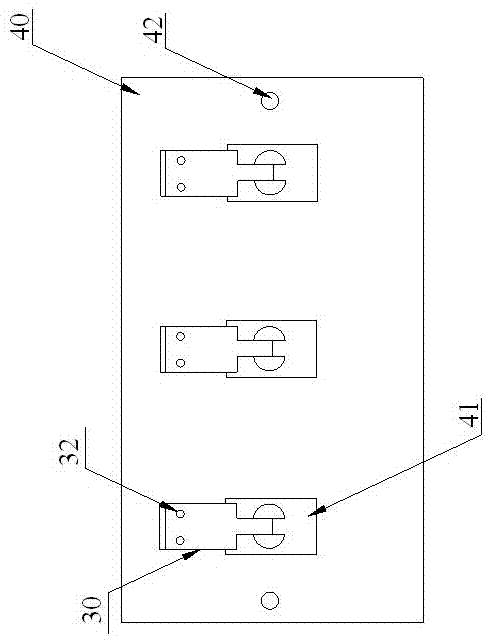
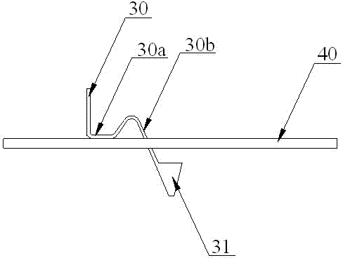
[0029] The hardware equipment required by the present invention includes an access panel 10, an electronic dust collector 20, an electrode sheet 30 and an electrode plate 40. The access panel 10 is arranged on the electronic dust collector 20, and the electrode sheet 30 is arranged on the electrode. On the plate 40, the electrode plate 40 is arranged on the side of the electronic dust collector 20 where the connected electr...


PUM


Abstract

The invention relates to a method for installing an electricity taking structure. The method is mainly used for electricity taking of an electronic dust collector. The method for installing the electricity taking structure comprises the following steps of arranging access electric plates, installing electrode slices and a plate electrode, assembling the access electric plates and the electrode slices, adjusting distances between the access electric plates and the plate electrode, and carrying out fixing and installation. A power input end of the electronic dust collector is provided with the three access electric plates. Joints of a power line and the three access electric plates are provided with the three electrode slices and the plate electrode. The plate electrode is provided with three through holes, wherein the electrode slices pass respectively through the three through holes. Through the cooperation of the electrode slices and the plate electrode, the electrode slices are elastically connected to the plate electrode and thus after compaction, in transportation and assembling, the spark phenomenon caused by poor contact in power up is avoided. The method is convenient for product assembling, dismounting and maintenance. In power on or power off, the method improves work efficiency by direct elastic connection.

Description

Technical field [0001] The invention relates to an installation method of a power taking structure, which is mainly used in the power taking aspect of an air purifier. Background technique [0002] Air purifiers, also known as "air cleaners" and "air fresheners", refer to the ability to absorb, decompose or transform various air pollutants (including dust, pollen, odor, formaldehyde and other decoration pollution). [0003] Air purifiers are small household appliances used to purify indoor air, mainly to solve indoor air pollution problems caused by decoration or other reasons. Since the release of pollutants in indoor air is persistent and uncertain, the use of air purifiers to purify indoor air is an internationally recognized method to improve indoor air quality. [0004] The working principle of the electronic dust collector in the air purifier is to use a high-voltage electric field to ionize the flue gas, and the dust in the airflow is separated from the airflow under the acti...

Claims


Application Information

Patent Timeline
Patent Type & Authority Patents(China)
IPC IPC(8): B03C3/40B03C3/66
Inventor 王飞叶佳
Owner ANHUI BINKEN ELECTRICAL CO LTD
Why Eureka
Try Eureka