Transmission locking device

A locking device and elastic device technology, applied in the direction of transmission, transmission parts, friction transmission, etc., can solve the problems of poor contact, stuck, skipped teeth, etc., and achieve low production cost, stable performance and convenient maintenance. Effect

Pending Publication Date: 2019-06-14
无锡市威博钟山科技有限公司
View PDF8 Cites 1 Cited by
  • Summary
  • Abstract
  • Description
  • Claims
  • Application Information

AI Technical Summary

Problems solved by technology

[0002] In the prior art, the transmission of machine tools mainly adopts screw nut pair and rack and pinion pair. Among them, the screw shaft is not suitable for long distances, and the rack can be extended freely. At the same time, the conventional rack and pinion pair has poor contact when moving. , jumping teeth, stuck when there are foreign objects, etc.

Method used


Image

  • Transmission locking device
  • Transmission locking device
  • Transmission locking device

Examples


Embodiment Construction

[0013] The present invention will be further described below in combination with specific embodiments and accompanying drawings.

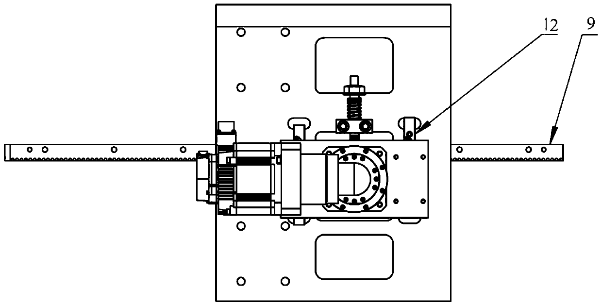
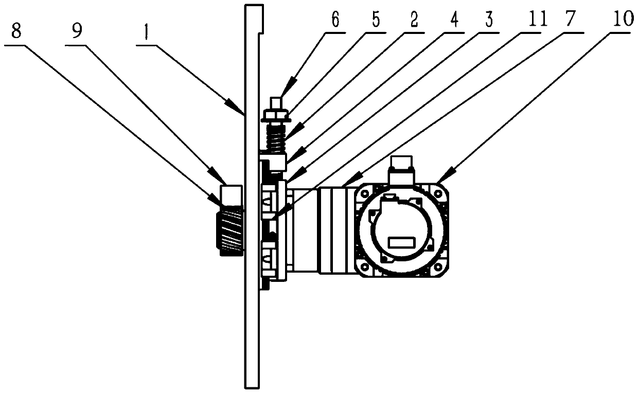
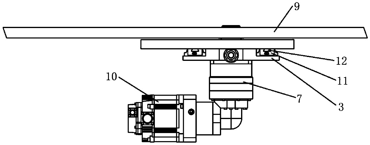
[0014] As shown in the figure: the transmission locking device includes a mounting plate 1, a servo motor 10, a reducer 7, a rack 9 and an elastic device. Wherein the servo motor 10 is connected with the reducer 7 and is slidably installed on the mounting plate 1 by the motor base 3 , and the output shaft of the reducer 7 is provided with a gear 8 . The gear 8 is pressed against the rack 9 by an elastic device, and the rack 9 and the elastic device are located on the same side of the gear 8. To ensure transmission accuracy, the gear 8 and the rack 9 adopt high-precision structures. The elastic device comprises a screw mandrel 6, a nut seat 4, a nut 5 and a spring 2, wherein the nut seat 4 is installed on the mounting plate 1, and one end of the screw mandrel 6 passes through the nut seat 4 to connect to the motor seat 3, and is used to drive the nu...


PUM


Abstract

The invention relates to a transmission mechanism, in particular to a transmission locking device. The device comprises a mounting plate, a servo motor, a speed reducer, a rack and an elastic device;the servo motor and the speed reducer are connected, the servo motor is arranged on the mounting plate through a motor base in a sliding manner, a gear is arranged on an output shaft of the speed reducer, the gear is arranged on the rack in a pressing and contact manner through the elastic device, the elastic device comprises a screw, a nut base, a nut and a spring, the nut base is arranged on themounting plate, one end of the screw penetrates through the nut base to be connected with the motor base, the other end of the screw is provided with the nut, and the position, between the nut base and the nut, of the screw is sleeved with the spring. The transmission locking device is simple in structure, convenient to maintain, low n manufacturing cost, stable in property, and free of poor contact, tooth jumping, clamping and the like.

Description

technical field [0001] The invention relates to a transmission mechanism, in particular to a transmission locking device, which is suitable for large and long machine tools. Background technique [0002] In the prior art, the transmission of machine tools mainly adopts screw nut pair and rack and pinion pair. Among them, the screw shaft is not suitable for long distances, and the rack can be extended freely. At the same time, the conventional rack and pinion pair has poor contact when moving. , jumping teeth, jamming when there are foreign objects and other defects. Contents of the invention [0003] The purpose of the present invention is to solve the above problems, and provides a transmission locking device, which is suitable for long-distance transmission, and has stable performance, and will not cause poor contact, tooth jumping, and jamming. [0004] According to the technical solution of the present invention, the transmission locking device includes a mounting pla...

Claims


Application Information

Patent Timeline
Patent Type & Authority Applications(China)
IPC IPC(8): F16H57/023F16H57/12F16H19/04H02K7/06
Inventor 徐刚
Owner 无锡市威博钟山科技有限公司
Why Eureka
Try Eureka