A large current step-by-step transfer switch for an aluminum electrolytic cell and a step-by-step current transfer method
What is AI technical title?
AI technical title is built by Patsnap AI team. It summarizes the technical point description of the patent document.
A transfer switch, aluminum electrolytic cell technology, applied in the field of current-on or off-current devices, can solve problems such as being less than ideal, and achieve the effects of simple structure, small footprint and low cost
Active Publication Date: 2015-07-29
ZHENGZHOU LIGHT METAL TECH
View PDF5 Cites 0 Cited by
Summary
Abstract
Description
Claims
Application Information
AI Technical Summary
This helps you quickly interpret patents by identifying the three key elements:
Problems solved by technology
Method used
Benefits of technology
Problems solved by technology
Therefore, the mode of opening and stopping the cell without power failure of the existing electrolyzer series is still not ideal enough
Method used
Image
Click on the blue label to locate the original text in one second.
Reading with bidirectional positioning of images and text.
Examples
Embodiment 1
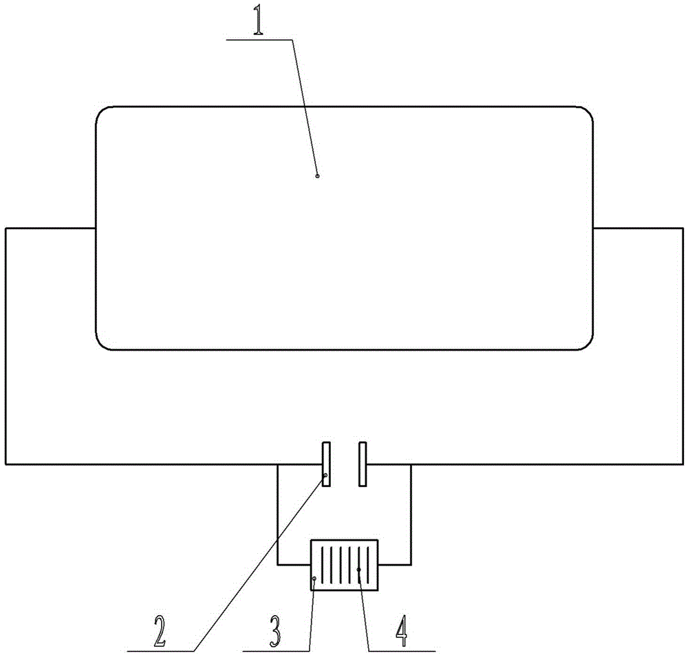
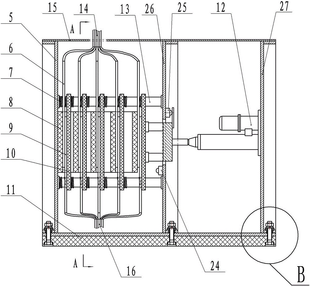
[0039] Embodiment 1: see figure 1 , figure 2 , image 3 , Figure 4 , Figure 5 , Figure 8 , Figure 9 , Figure 10 , Figure 11 , Figure 12 , Figure 13 , Figure 14 , Figure 15 , Figure 16 As shown, a step-by-step high current transfer switch for an aluminum electrolytic cell includes a support plate, a sealing cover plate 15, a switch upper and lower contact connecting plate 4, an insulating frame 8, an insulating movable crimping plate 10, and an electro-hydraulic push rod 12. The insulating base 11, the electric push rod 12 is closed and separated between the upper and lower contact connecting plates 4 of the motor synchronous forward and reverse control switch, and two are respectively fixed between the left support plate 5 and the middle support plate 26. The middle upper horizontal support shaft and the two middle lower horizontal support shafts with an insulating layer are provided with at least one pair of switch upper and lower contact connecting pl...
Embodiment 2
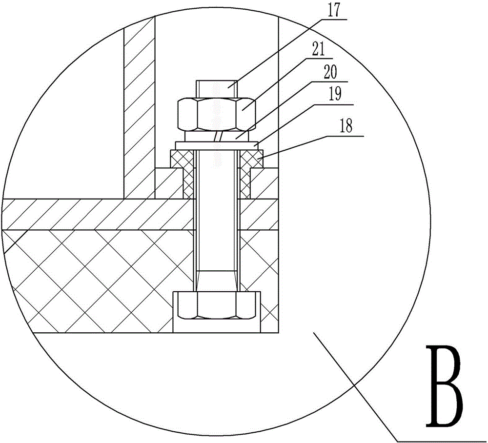
[0043] Example 2: see figure 1 , Figure 6 , Figure 7 , Figure 8 , Figure 9 , Figure 10 , Figure 11 , Figure 12 , Figure 13 , Figure 14 , Figure 15 , Figure 16 , Figure 17 , Figure 18 As shown, the symbols in the figure that are the same as those in Embodiment 1 have the same meaning, and the same parts as those in Embodiment 1 will not be repeated. The difference is that the power moving mechanism is a rack and pinion transmission mechanism 23, and the gear The rack drive mechanism 23 is set on the support platform 22, and the upper and lower contact connecting plates of the switch are shaped as two-phase alternating and matching broken-line switch upper contact connecting plates 6a and lower contact connecting plates 9a, that is, the two phases are mutually matched. The upper and lower contact connecting plates of the broken-line switch are two intersecting and matching broken-line contact plates of two triangles with a common side, or two matching br...
Embodiment 3
[0044] Embodiment 3: The same parts as in Embodiment 1 will not be repeated, the difference is: the power moving mechanism is an electric worm gear mechanism composed of a servo motor, a worm gear, and a worm.
PUM
Abstract
The invention relates to a device for realizing on / off of current by need of step-by-step transferring of current on certain equipment under the condition that the system is not powered off or the current is not reduced in a direct-current and large-current series circuit system, and particularly relates to a large-current step-by-step transferring switch for an aluminium electrolysis cell and a step-by-step current transferring method. The large-current step-by-step transferring switch comprises a supporting plate, a sealing cover plate, connecting plates of an upper contact and a lower contact of the switch, an insulated frame, an insulated movable pressing and connecting plate, a power moving mechanism and an insulated base, wherein the power moving mechanism and all the switches control the connection and separation of the connecting plates by synchronous forward-reverse rotation of a motor. The device and the method have the advantages that the weight is light, the use is safe and convenient, the occupied space is small, the working is reliable, the manufacturing cost is low, the installation is not influenced by the magnetic field of an electrolytic bath, and the thickness, the area and the materials of the connecting plates can be determined according to the requirement of the partial current design.
Description
technical field [0001] The invention relates to a device in a DC high-current series circuit system that needs to transfer the current on one of the devices step by step to realize current passing or cutting under the condition of continuous power supply or current reduction in the system, especially relates to a device A step-by-step transfer switch for a large current used in an aluminum electrolytic cell and a step-by-step transfer method for a current. Background technique [0002] An aluminum electrolysis series is usually composed of hundreds of electrolytic cells connected in series. The series voltage is high and the current is large. When one electrolytic cell in the series is powered off or powered on due to overhaul or other reasons, it needs to be operated under the power failure state of the series. Series of power outages not only impact the power grid, but also interfere with the operation of the electrolyzer, affecting production indicators and shortening the...
Claims
Application Information
Patent Timeline
Application Date:The date an application was filed.
Publication Date:The date a patent or application was officially published.
First Publication Date:The earliest publication date of a patent with the same application number.
Issue Date:Publication date of the patent grant document.
PCT Entry Date:The Entry date of PCT National Phase.
Estimated Expiry Date:The statutory expiry date of a patent right according to the Patent Law, and it is the longest term of protection that the patent right can achieve without the termination of the patent right due to other reasons(Term extension factor has been taken into account ).
Invalid Date:Actual expiry date is based on effective date or publication date of legal transaction data of invalid patent.

