Large-current step-by-step transferring switch for aluminium electrolysis cell and step-by-step current transferring method

A transfer switch and aluminum electrolytic cell technology, applied in the field of current-on or off-current devices, can solve problems such as unsatisfactory, and achieve the effect of simple structure, low cost, safe and reliable operation

Active Publication Date: 2013-07-17
ZHENGZHOU LIGHT METAL TECH
View PDF5 Cites 0 Cited by
  • Summary
  • Abstract
  • Description
  • Claims
  • Application Information

AI Technical Summary

Problems solved by technology

Therefore, the mode of opening and stopping the cell without power failure of the existing electrolyzer series is still not ideal enough

Method used


Image

  • Large-current step-by-step transferring switch for aluminium electrolysis cell and step-by-step current transferring method
  • Large-current step-by-step transferring switch for aluminium electrolysis cell and step-by-step current transferring method
  • Large-current step-by-step transferring switch for aluminium electrolysis cell and step-by-step current transferring method

Examples


Embodiment 1

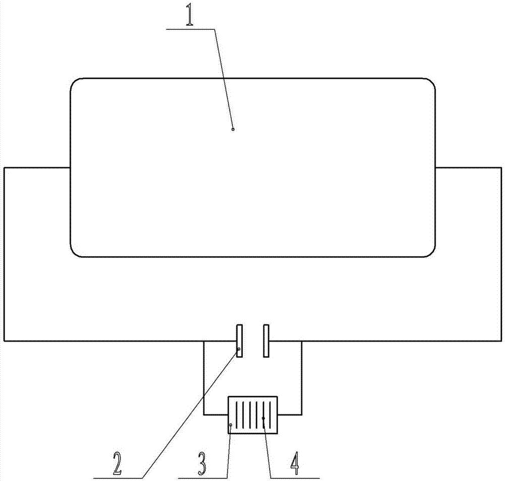
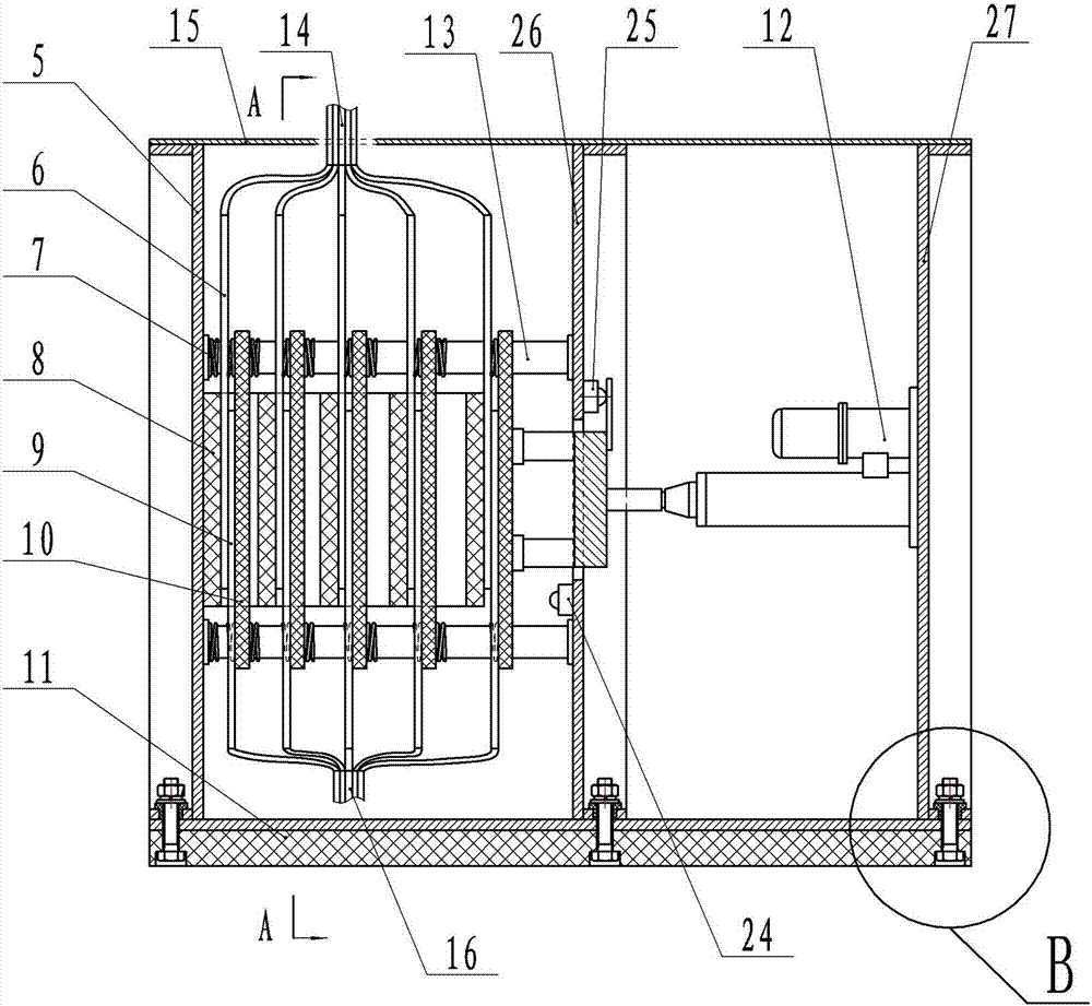
[0039] Example 1: see figure 1 , figure 2 , image 3 , Figure 4 , Figure 5 , Figure 8 , Figure 9 , Figure 10 , Figure 11 , Figure 12 , Figure 13 , Figure 14 , Figure 15 , Figure 16 As shown, a high-current step-by-step transfer switch for an aluminum electrolytic cell includes a support plate, a sealing cover plate 15, a switch upper and lower contact connecting plate 4, an insulating frame 8, an insulating movable crimping plate 10, and an electro-hydraulic push rod. 12, the insulating base 11, the electric push rod 12 controls the closing and separation between the upper and lower contact connecting plates 4 through the motor synchronous forward and reverse control switch, and two are fixed between the left support plate 5 and the middle support plate 26 respectively. The middle-upper horizontal support shaft and the two middle-lower horizontal support shafts with insulating layer are provided with at least one pair of switch upper and lower contact c...

Embodiment 2

[0043] Example 2: see figure 1 , Image 6 , Figure 7 , Figure 8 , Figure 9 , Figure 10 , Figure 11 , Figure 12 , Figure 13 , Figure 14 , Figure 15 , Figure 16 , Figure 17 , Figure 18 As shown in the figure, the symbols in the figures have the same meanings as those in Embodiment 1, and the same parts as those in Embodiment 1 will not be repeated. The difference is that the power moving mechanism is a rack and pinion transmission mechanism 23, The rack transmission mechanism 23 is arranged on the support platform 22, and the upper and lower contact connecting plates of the switch are in the shape of the upper contact connecting plate 6a and the lower contact connecting plate 9a of the two-phase switch which are mutually matched, that is, the two phases are mutually matched. The upper and lower contact connecting plates of the folded-line switch are folded-line contact connecting plates in which two triangles with a common side are matched with each other...

Embodiment 3

[0044] Embodiment 3: The same parts as those in Embodiment 1 will not be repeated, the difference is: the power moving mechanism is an electric worm gear mechanism composed of a servo motor, a worm gear, and a worm.


PUM


Abstract

The invention relates to a device for realizing on/off of current by need of step-by-step transferring of current on certain equipment under the condition that the system is not powered off or the current is not reduced in a direct-current and large-current series circuit system, and particularly relates to a large-current step-by-step transferring switch for an aluminium electrolysis cell and a step-by-step current transferring method. The large-current step-by-step transferring switch comprises a supporting plate, a sealing cover plate, connecting plates of an upper contact and a lower contact of the switch, an insulated frame, an insulated movable pressing and connecting plate, a power moving mechanism and an insulated base, wherein the power moving mechanism and all the switches control the connection and separation of the connecting plates by synchronous forward-reverse rotation of a motor. The device and the method have the advantages that the weight is light, the use is safe and convenient, the occupied space is small, the working is reliable, the manufacturing cost is low, the installation is not influenced by the magnetic field of an electrolytic bath, and the thickness, the area and the materials of the connecting plates can be determined according to the requirement of the partial current design.

Description

technical field [0001] The present invention relates to a device that needs to transfer the current on a certain device step by step to realize current on or off in the case of uninterrupted power or current drop in a DC high current series circuit system, in particular to a device A large current step-by-step transfer switch for an aluminum electrolytic cell and a current step-by-step transfer method. Background technique [0002] An aluminum electrolysis series is usually composed of hundreds of electrolytic cells connected in series, with high voltage and high current. The series of power outages not only caused an impact on the power supply grid, but also interfered with the operation of the electrolyzer, affecting the production indicators and shortening the life of the electrolyzer. [0003] For a long time, the international and domestic aluminum industry has been carrying out the research and practice of the shutdown and opening of the electrolytic cell under the co...

Claims


Application Information

Patent Timeline
Patent Type & Authority Applications(China)
IPC IPC(8): C25C3/16C25C3/06
Inventor 刘静冯冰廉凯
Owner ZHENGZHOU LIGHT METAL TECH
Why Eureka
Try Eureka