Device for automatic correcting telescope astigmatic aberration using telescope second lens

An automatic correction and telescope technology, applied in optics, instruments, optical components, etc., to achieve the effect of fast speed, high performance, and improved integration level

Inactive Publication Date: 2010-06-30
INST OF OPTICS & ELECTRONICS - CHINESE ACAD OF SCI
View PDF3 Cites 0 Cited by
  • Summary
  • Abstract
  • Description
  • Claims
  • Application Information

AI Technical Summary

Problems solved by technology

[0027] The technology of the present invention solves the problem: overcomes the deficiencies of the existing technologies for compensating the static and quasi-static aberrations of the reflective telescope system, and provides a method for automatically correcting the telescope aberration without measuring various static and quasi-static aberrations of the reflective telescope system With this device, there is no need to add aberration compensation devices outside the reflecting telescope, but a deformable mirror is cleverly used as the secondary mirror of the reflecting telescope, which has the advantages of compact system and simple structure, and can automatically compensate the system aberration of the reflecting telescope , can greatly improve the imaging capability of the reflecting telescope

Method used


Image

  • Device for automatic correcting telescope astigmatic aberration using telescope second lens
  • Device for automatic correcting telescope astigmatic aberration using telescope second lens
  • Device for automatic correcting telescope astigmatic aberration using telescope second lens

Examples


Embodiment Construction

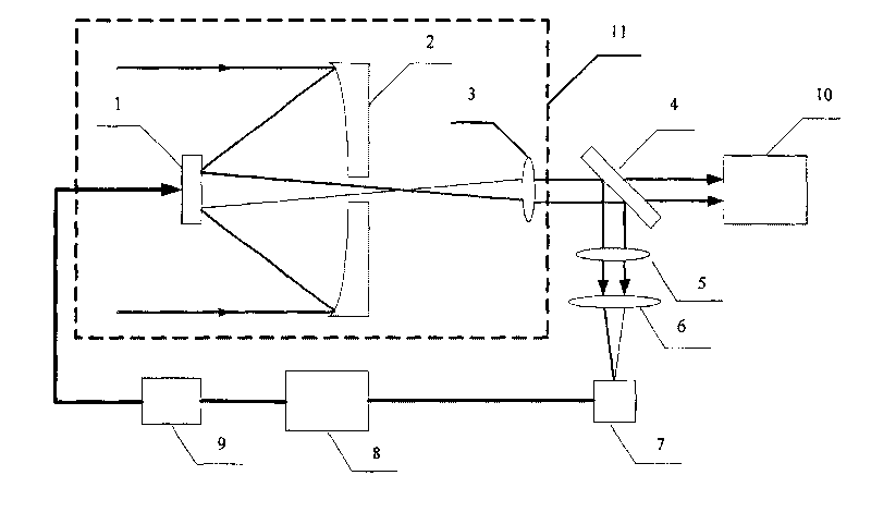
[0052] Such as figure 1 As shown, the light from the object to be observed is received by the primary mirror 2 of the reflecting telescope system 11. A piezoelectric ceramic deformable mirror is used as the secondary mirror 1 of the reflecting telescope system 11 to gather the light on the primary mirror 2 of the reflecting telescope system 11 Before the focus; then the light passes through a circular hole of the main mirror 2 and is focused behind the main mirror 2, and then becomes parallel or nearly parallel by the eyepiece 3 of the reflecting telescope system 11, and then the light is divided into two beams by the beam splitter 4 , A beam is imaged on the monitor 10 for observation; a beam is attenuated by the variable-density attenuation disk 5 and then incident on the focusing lens 6, is focused by the lens 6 and incident on the CCD camera 7 placed on the focal plane of the lens 6, in A soft diaphragm is set on the target surface of the CCD camera 7, and the diaphragm is ...


PUM


Abstract

The device is mainly composed of reflecting telescope system, beam splitter, variable density attenuation disc, high voltage amplifier, CCD camera, data acquisition system, industrial control computer, and software control system based on genetic algorithm. Using secondary mirror of the reflecting telescope being as wave front phase corrector, the invention can adjust alignment between primary mirror and secondary mirror of the reflecting telescope automatically under condition of not introducing additional part of aberrational correction. The invention can corrects static and quasi-static aberration of the reflecting telescope as well as aberration brought by each optical part self in selfadaption. Advantage are: compact structure, simple control, and easy of implementation. The invention reduces system error of reflecting telescope imaging greatly, raises imaging capability of the telescope.

Description

Technical field [0001] The invention relates to an adaptive optics device, in particular to an adaptive optics device based on genetic algorithm for correcting telescope aberration, automatically aligning the telescope system, and improving the imaging capability of the telescope system. Background technique [0002] As one of the most important inventions in astronomy, the telescope has a history of nearly four hundred years since its inception in 1609, during which the development of the telescope has experienced a major leap. According to the type of objective lens, telescopes can be divided into three types: namely, refracting telescope, reflecting telescope and catadioptric telescope. But the most used astronomy is the reflecting telescope, especially the Cassegrain reflecting telescope. Reflecting telescopes use a metal (usually aluminum) concave glass as the primary mirror to receive and focus light. Since the focal point is in front of the mirror, a Convex hyperboloid is...

Claims


Application Information

Patent Timeline
Patent Type & Authority Patents(China)
IPC IPC(8): G02B26/06G02B27/00G06N3/12
Inventor 杨平许冰杨伟胡诗杰陈善球姜文汉
Owner INST OF OPTICS & ELECTRONICS - CHINESE ACAD OF SCI
Why Eureka
Try Eureka