Power steering apparatus

A technology of power steering device and power cylinder, applied in power steering mechanism, steering mechanism, fluid steering mechanism, etc., can solve problems such as abnormality and noise

Inactive Publication Date: 2007-07-04
HITACHI LTD
View PDF2 Cites 6 Cited by
  • Summary
  • Abstract
  • Description
  • Claims
  • Application Information

AI Technical Summary

Problems solved by technology

In such a power steering device, there is a problem of abnormal noise due to the impact noise generated by interruption of hydraulic fluid flow

Method used


Image

  • Power steering apparatus
  • Power steering apparatus
  • Power steering apparatus

Examples


Embodiment Construction

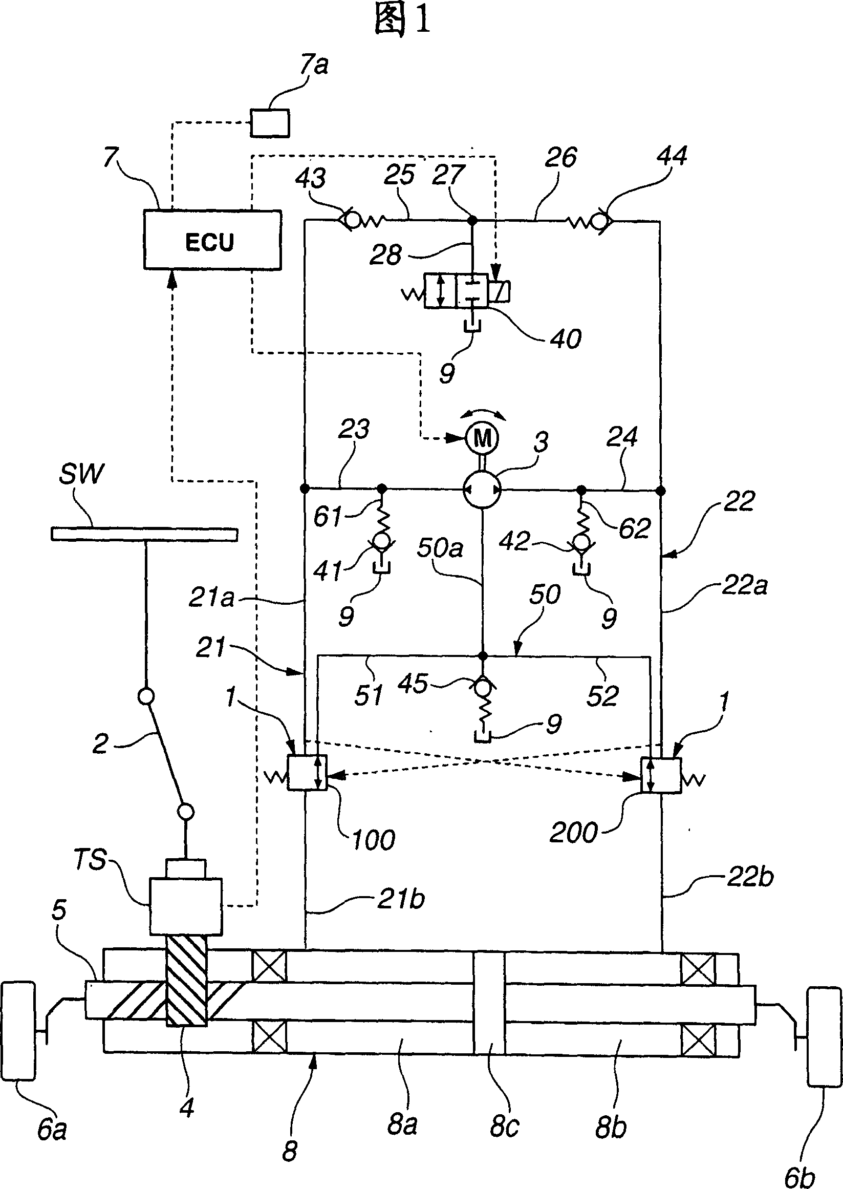
[0028] [Power Steering System Configuration] FIG. 1 is a view showing a system configuration of a power steering apparatus according to a first embodiment of the present invention. When the driver operates the steering wheel SW, the pinion 4 is driven via the shaft 2 . Then, the rack shaft 5 is moved in the axial direction by a rack-and-pinion mechanism (steering mechanism) to steer the front wheels. A torque sensor TS is provided at the shaft 2, which is configured to detect a driver's steering torque, and to output a torque signal to a control device 7 (motor control section).

[0029] The rack shaft 5 is provided with a power steering mechanism configured to assist the movement of the rack shaft 5 in accordance with a driver's steering torque. The power steering mechanism includes a bidirectional pump 3 driven by a motor M and a power cylinder 8 arranged to move the rack shaft 5 toward right and left (as shown in FIG. 1 ).

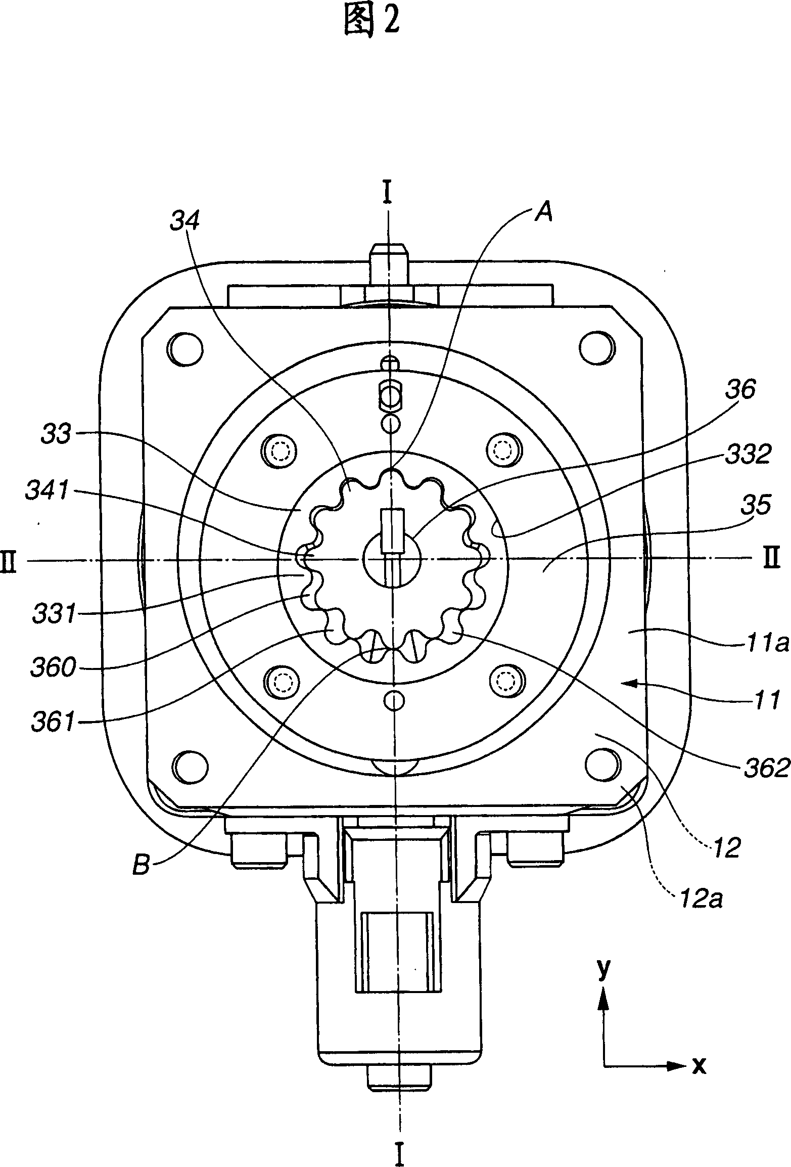
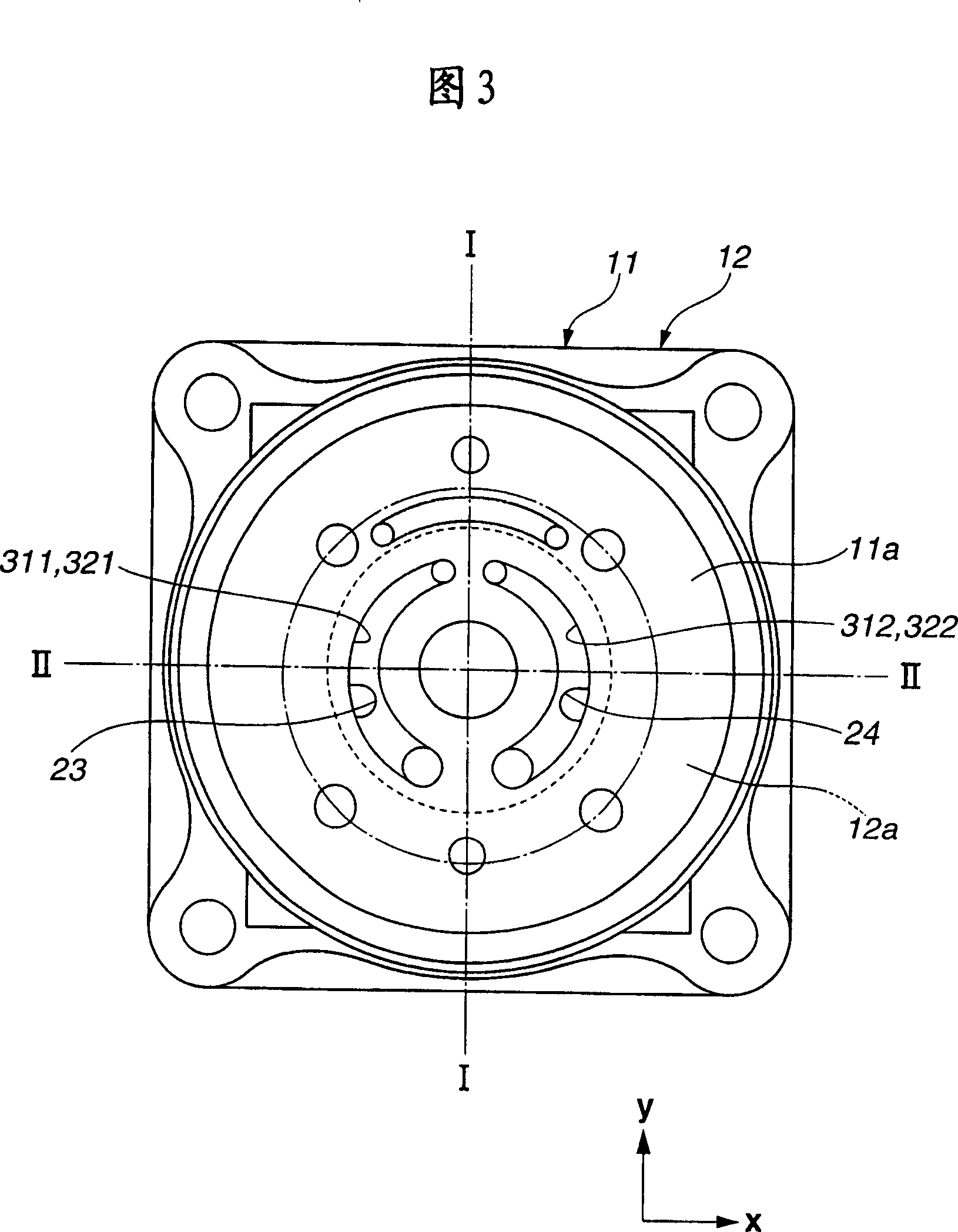
[0030] As shown in FIG. 3 , the bidirectional p...


PUM


Abstract

A power steering apparatus includes a power cylinder including first and second pressure chambers, a hydraulic pump including first and second discharge ports, the hydraulic pump being arranged to supply a hydraulic pressure selectively to the first and second pressure chambers; first and second hydraulic passages connecting the first and second pressure chambers and the first and second discharge ports; a motor arranged to drive the hydraulic pump; a motor control section configured to output a drive signal to the motor; a reservoir tank storing a hydraulic fluid; first and second bypass passages connecting the first and second hydraulic passages and the reservoir tank; first and second bypass valves arranged to open and close the first and second bypass passages; and first and second flow rate restricting sections disposed in the first and second bypass passages, and arranged to decrease flow rates of the first and second bypass passages.

Description

technical field [0001] The invention relates to a hydraulic power steering device. Background technique [0002] U.S. Patent Application Publication 2005 / 00 230 73 (A1) (equivalent to Japanese Patent Application Publication 2003-047296) shows a power steering device, which includes an electric motor, a power cylinder and a bidirectional pump. The power cylinder has a left cylinder and the right cylinder, while the above-mentioned bidirectional pump is driven by an electric motor, and is configured to selectively supply hydraulic pressure to the left cylinder and the right cylinder so that the power steering device obtains steering assist force. [0003] For example, in a case where hydraulic pressure is supplied to the right cylinder, the pressure in the right hydraulic passage is raised especially in a state of abutting against the handle, thereby expanding the right hydraulic passage. The volume of the piping system increases due to expansion, so the hydraulic fluid is in...

Claims


Application Information

Patent Timeline
Patent Type & Authority Applications(China)
IPC IPC(8): B62D5/06
CPCB62D5/062B62D5/065
Inventor 仓田昌和榊敏光
Owner HITACHI LTD
Why Eureka
Try Eureka