Plane display device

A flat display and bracket technology, applied in the direction of instruments, instrument parts, supporting machines, etc., can solve the problems of angle adjustment restrictions, inability to meet angle changes, and difficult height adjustment, etc., to achieve the effect of easy operation

Inactive Publication Date: 2007-07-04
LG ELECTRONICS(NANJING) PLASMA CO LTD
View PDF0 Cites 13 Cited by
  • Summary
  • Abstract
  • Description
  • Claims
  • Application Information

AI Technical Summary

Problems solved by technology

[0006] However, once this traditional flat display device 1 is hung on the wall and fixed, if you want to adjust its height, you need to remove the above-mentioned first bracket 2 from the wall and hang it again, so there is a problem that it is difficult to adjust the height. In addition, although the above-mentioned first bracket 2 can be equipped with a simple hinge device (not shown) to adjust the angle, it cannot meet the requirements of angle change.
[0007] In addition, as shown in Figure 1b, when using a bracket composed of a support bracket 4 and a second bracket 3, the height of the bracket is also limited when adjusting the maximum height. In this case, the angle adjustment is also limited.

Method used


Image

  • Plane display device
  • Plane display device
  • Plane display device

Examples


Embodiment 1

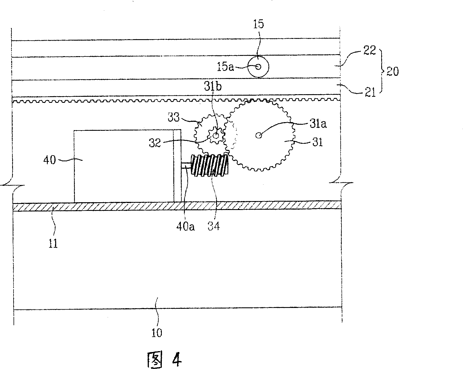
[0026] First, the structure of the first embodiment of the present invention will be described with reference to FIGS. 2 to 4 . In the present invention, the plane display device is composed of the following parts: the body 10 forming the shape; the bracket 11 attached to the rear side of the body 10; the pinion gear 31 which is arranged on the bracket 11 and can rotate; On the rear side of the body 10 , a drive motor 40 that rotates the pinion gear 31 ; and a rail portion 20 that is connected to the bracket 11 and moves relative to the bracket 11 .

[0027] One side of the rail portion 20 is constituted by a rack and pinion 21 .

[0028] In addition, the side on which the rack gear 21 is formed is centered, and both sides are formed by guide grooves 22. The bracket 11 is equipped with a guide wheel 15, and the guide wheel 15 is inserted into the guide groove 22 so as to be rotatable.

[0029] The above-mentioned bracket 10 is equipped with a rotating shaft 31a that crosses t...

Embodiment 2

[0042] On the other hand, FIG. 5 is a block diagram showing the relationship among main components of a flat-panel display device according to a second embodiment of the present invention.

[0043] Below, the parts that have the same structure as the first embodiment of the present invention will be described by citing the same drawing numbers. In addition, the description of the same structure as the first embodiment has been described in detail in the first embodiment. description, so a more detailed description of its parts is omitted.

[0044] First, the configuration of a flat panel display device according to a second embodiment of the present invention will be described with reference to FIG. 5 . It consists of the following parts: a body 10; a bracket 11 attached to the rear side of the body 10; a secondary gear 31 that is arranged on the bracket 11 and can rotate; The drive motor 40 that the gear 31 rotates; the control unit 80 that is arranged on the above-mentioned...


PUM


Abstract

The invention discloses a plan display device that comprises: body which forms the appearance; bracket which is adhered to back of the said body; duplicate gear which is mounted on said bracket and can rotate; drive motor which is mounted on back of said body and make said duplicate gear rotate; track part which is connected with said bracket and shifts relatively to said bracket; besides, the invention also provides a plan display device which includes control part which is mounted on said body of said plan display device and electric connected with said drive motor; signal transmitting part which sends scheduled frequency signal that permits said drive motor to start to said control part. The invention can adjust the height and angle of the plan display device; it is operated by report controller, so it possesses effect of easy to operate.

Description

technical field [0001] The invention relates to a flat display device such as a monitor, and more specifically relates to a method for connecting the flat display device to a track so that it can not only move vertically along the indoor wall surface, but also make it move to the ceiling, so it is more convenient to adjust its height and angle. Background technique [0002] Generally speaking, household electrical appliances such as flat panel display devices are fixedly arranged on the ground or on the wall by means of brackets. [0003] A conventional flat panel display device configured as above is shown in FIG. 1a and FIG. 1b. [0004] First of all, FIG. 1a is a diagram roughly showing the state when the traditional flat display device is hung on the wall, and FIG. 1b is a diagram roughly showing the state when the traditional flat display device is installed on the ground with a stand. [0005] That is, in the conventional way, as shown in FIG. 1a, the flat panel disp...

Claims


Application Information

Patent Timeline
IPC IPC(8): G12B9/08F16M13/00
Inventor 金议正
Owner LG ELECTRONICS(NANJING) PLASMA CO LTD
Why Eureka
Try Eureka