
Detecting and adjusting device for display color temperature and method therefor

A display and color temperature technology, which is applied to measurement devices, static indicators, cathode ray tube indicators, etc., can solve problems such as shortening time, negative impact on display production efficiency, inconvenient display color temperature inspection and adjustment devices and methods, etc. The effect of efficiency

Inactive Publication Date: 2007-07-11
INVENTEC CORP
View PDF1 Cites 24 Cited by
  • Summary
  • Abstract
  • Description
  • Claims
  • Application Information

AI Technical Summary

Problems solved by technology

[0006] In the first stage of this prior art, a wireless transmission link is used to replace the wired transmission link, which can shorten the time required to achieve the connection between the computer system and the display in the first stage. Sensing is achieved through the control of the computer system. However, there is still a changeable means that can also achieve its purpose, that is, the display can display a picture without being controlled by the computer, which is used for the display to locate to the color temperature. Color temperature sensing can be performed immediately after calibration to save the computer system control program
[0007] In this prior art, a single computer system performs color temperature adjustment on a single display when adjusting the color temperature. This color temperature adjustment method cannot be used for computer systems with a large number of computing functions, and it is not effective for the overall display. There is also a negative impact on productivity
[0008] It can be seen that the above-mentioned existing display color temperature inspection and adjustment device and method obviously still have inconvenience and defects, and need to be further improved urgently.

Method used


Image

  • Detecting and adjusting device for display color temperature and method therefor
  • Detecting and adjusting device for display color temperature and method therefor
  • Detecting and adjusting device for display color temperature and method therefor

Examples


Embodiment Construction

[0044] In order to further explain the technical means and effects of the present invention to achieve the intended purpose of the invention, the specific implementation, structure, The test method, steps, characteristics and efficacy are described in detail below.

[0045] The above description of the content of the present invention and the following description of the specific implementation methods are used to demonstrate and explain the spirit and principle of the present invention, and to provide further explanation of the patent application scope of the present invention.

[0046] The following four specific embodiments of the present invention are listed below, each of which can be implemented by display manufacturers.

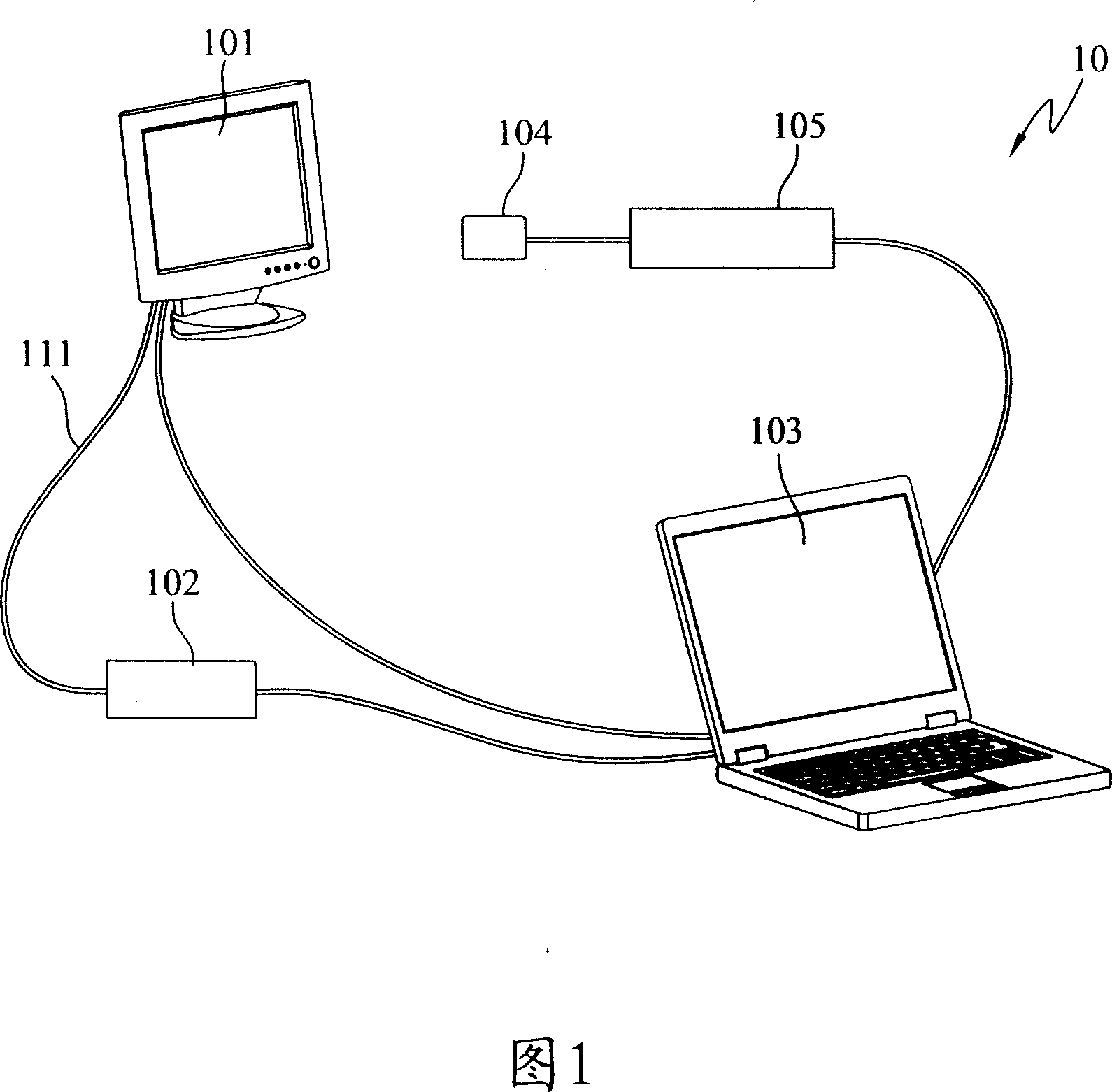
[0047] Please refer to FIG. 1 , which is a schematic diagram of a first preferred embodiment of a display color temperature checking and calibrating device of the present invention. In the implementation of the first preferred embodiment of the presen...


PUM


Abstract

The invention relates to a display color temperature inspection adjusting device. It comprises signal generator, color temperature detector, color analyzer, and computer system. The display color temperature adjusting method comprises generating an image signal, sending image signal to display, displaying an image, detecting image color temperature, generating No. 1 color temperature detecting value, sending No. 1 color temperature detecting value to computer system, and comparing No. 1 color temperature detecting value with the preset value by the computer system. It is used to on line color temperature inspection calibration with signal generator and accumulator, with the signal generator providing signal to the display, free from computer system inputting signal to display for color temperature inspection and calibration, accumulating device to connect several display to be adjusted to the computer system, color inspecting for several display and adjusting, with improved efficiency of on line color temperature adjusting operation.

Description

technical field [0001] The present invention relates to a display color temperature inspection and adjustment device and method, in particular to a display color temperature inspection and adjustment device and method for a color temperature inspection and adjustment station used in a display production line to check and adjust the color temperature of a display. Background technique [0002] At present, the OSD (On Screen Display) of the display has the option of color temperature, which is convenient for personal preference to choose different color temperature results. In order to make the color temperature of each factory display consistent, the display manufacturer must implement automatic adjustment. The color temperature calibration operation is used to control the color temperature adjustment of the monitor. The previous prior art of known automatic color temperature adjustment operation, for example: China Taiwan Patent Gazette on October 11, 1993 announced the No. ...

Claims


Application Information

Patent Timeline
IPC IPC(8): G09G3/00G09G5/02G01R31/00G02F1/13G01M11/00H04N17/02
Inventor 庄淑雯
Owner INVENTEC CORP
Learn More