Check patentability & draft patents in minutes with Patsnap Eureka AI!

Plasma display apparatus

A display device and plasma technology, applied in static indicators, clay preparation devices, identification devices, etc., can solve problems such as misdischarge of light-emitting points, wall charges not erased, etc.

Inactive Publication Date: 2007-07-11
LG ELECTRONICS INC
View PDF0 Cites 0 Cited by
  • Summary
  • Abstract
  • Description
  • Claims
  • Application Information

AI Technical Summary

Problems solved by technology

[0010] However, it is disadvantageous in that, although the fall time (Tf) of the last sustain pulse is set to about 600 ns, when the last sustain pulse (SP) is applied, excessively formed wall charges are not sufficiently erased from the discharge cell, and generation Misdischarge of luminescent spot

Method used


Image

  • Plasma display apparatus
  • Plasma display apparatus
  • Plasma display apparatus

Examples


Embodiment Construction

[0024] Preferred embodiments of the present invention will now be described in more detail with reference to the accompanying drawings.

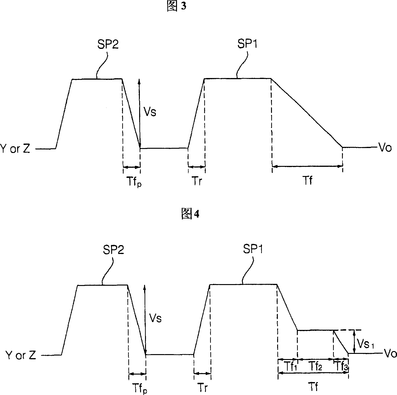
[0025] FIG. 3 illustrates driving waveforms of the plasma display device according to the first embodiment of the present invention.

[0026] The inventive plasma apparatus includes a first electrode at an upper substrate and a driver for applying a driving signal to the first electrode. By the driving waveform applied by the driver, discharge is generated and an image is displayed.

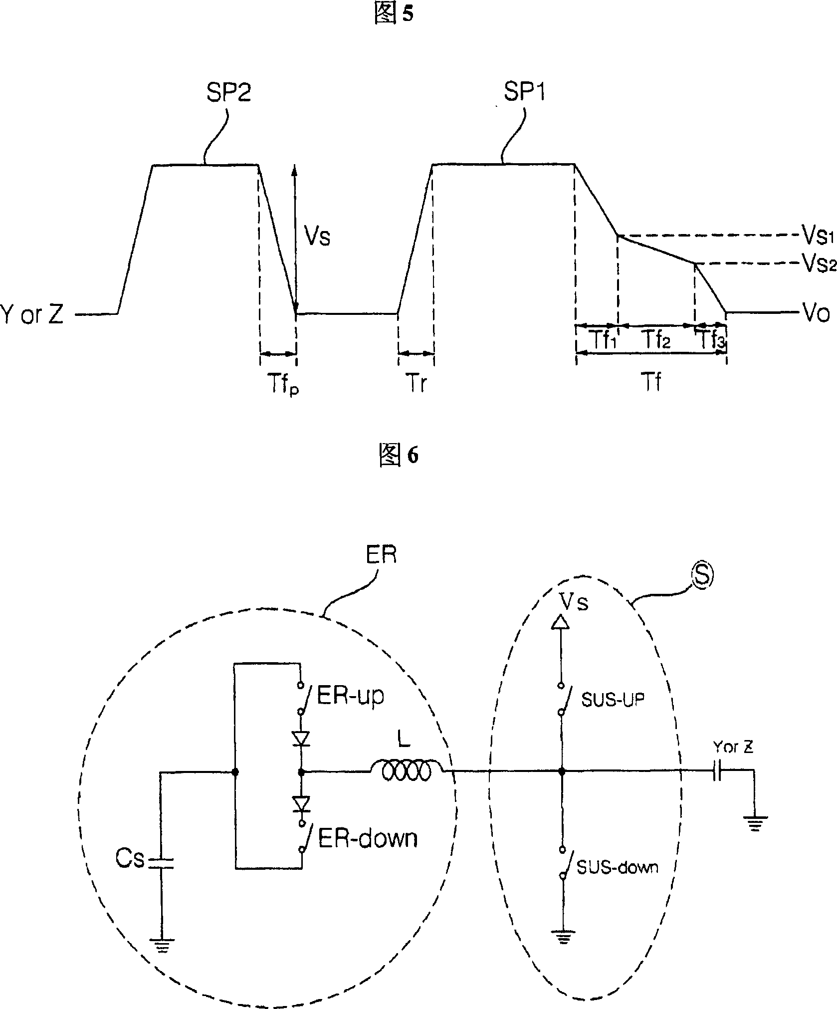
[0027] The first electrode may be any one of a scan electrode and a sustain electrode. The driver refers to a scan electrode driver or a sustain electrode driver corresponding to the first electrodes.

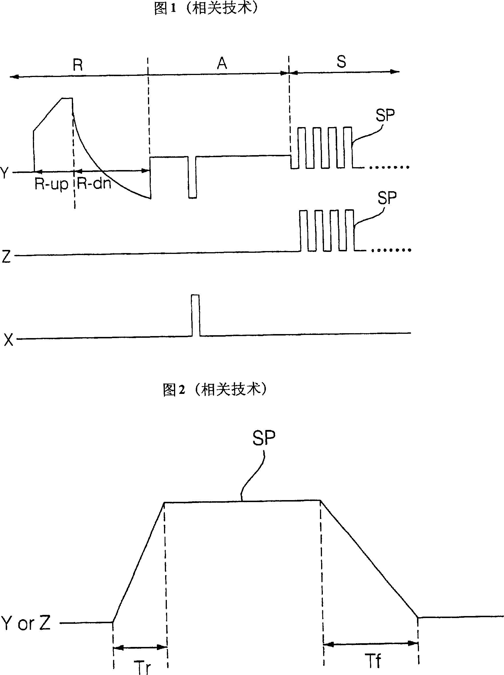
[0028] A plasma display device is driven by one frame divided into a plurality of subfields. Each subfield includes: a reset period for initializing the discharge cells of the entire screen; an address period for selecting a discharge cell; a sustain period f...


PUM


Abstract

Provided a plasma display apparatus. The apparatus includes a first electrode and a driver. The first electrode is formed at an upper substrate. The driver applies a sustain pulse to the first electrode. The driver applies a driving waveform whose, in one subfield, any one sustain pulse (SP1) has a longer falling time than another sustain pulse (SP2) applied earlier than the sustain pulse (SP1).

Description

technical field [0001] The present invention relates to a plasma display device, and more particularly, to a plasma display device for prolonging the falling time of a sustain pulse applied at the end of a sustain period and partially erasing the excessively formed discharge cell. The internal wall charge, thereby preventing misdischarge. Background technique [0002] FIG. 1 illustrates driving waveforms for driving a conventional plasma display device, and FIG. 2 illustrates sustain pulses applied at the end of a sustain period in the conventional plasma display device. [0003] As shown in FIG. 1, the driving waveform includes: a reset period (R), an address period (A) and a sustain period (S). During the reset period, a setup reset signal (R-up) and a setup down reset signal (R-dn) are sequentially supplied. If the set-up reset signal (R-up) is supplied, a reset discharge is generated between the scan electrode (Y) and the sustain electrode (Z), and wall charges are sto...

Claims


Application Information

Patent Timeline
Patent Type & Authority Applications(China)
IPC IPC(8): G09G3/28G09G3/20H01J17/49G09F9/313G09G3/288G09G3/292G09G3/294
CPCG09G3/294G09G2310/066G09G3/2927B28C9/0454B28C5/4203B28C7/04B28C7/022
Inventor 郑奉燮
Owner LG ELECTRONICS INC
Features
  • R&D
  • Intellectual Property
  • Life Sciences
  • Materials
  • Tech Scout
  • Unparalleled Data Quality
  • Higher Quality Content
  • 60% Fewer Hallucinations
Learn More