Check patentability & draft patents in minutes with Patsnap Eureka AI!

Structure of scanner core

A scanner and lens technology, applied in the field of movement structure with dual light sources and switchable light paths, can solve the problems of increasing the volume of the scanner 1, and achieve the effect of reducing space and volume

Inactive Publication Date: 2007-07-11
PRIMAX ELECTRONICS LTD
View PDF0 Cites 1 Cited by
  • Summary
  • Abstract
  • Description
  • Claims
  • Application Information

AI Technical Summary

Problems solved by technology

[0003] Continue to refer to FIG. 1A and FIG. 1B , but the common scanner 1 still adopts the same movement structure 10 as the flatbed scanner, so when it is necessary to perform paper-fed scanning, the movement structure 10 must be completely moved to Scanning can only be performed under the scanning window 11. Unavoidably, some placement space 12 must be reserved in the scanner 1 to place the movement structure 10 for paper-fed scanning, thus increasing the volume of the entire scanner 1.

Method used


Image

  • Structure of scanner core
  • Structure of scanner core
  • Structure of scanner core

Examples


Embodiment Construction

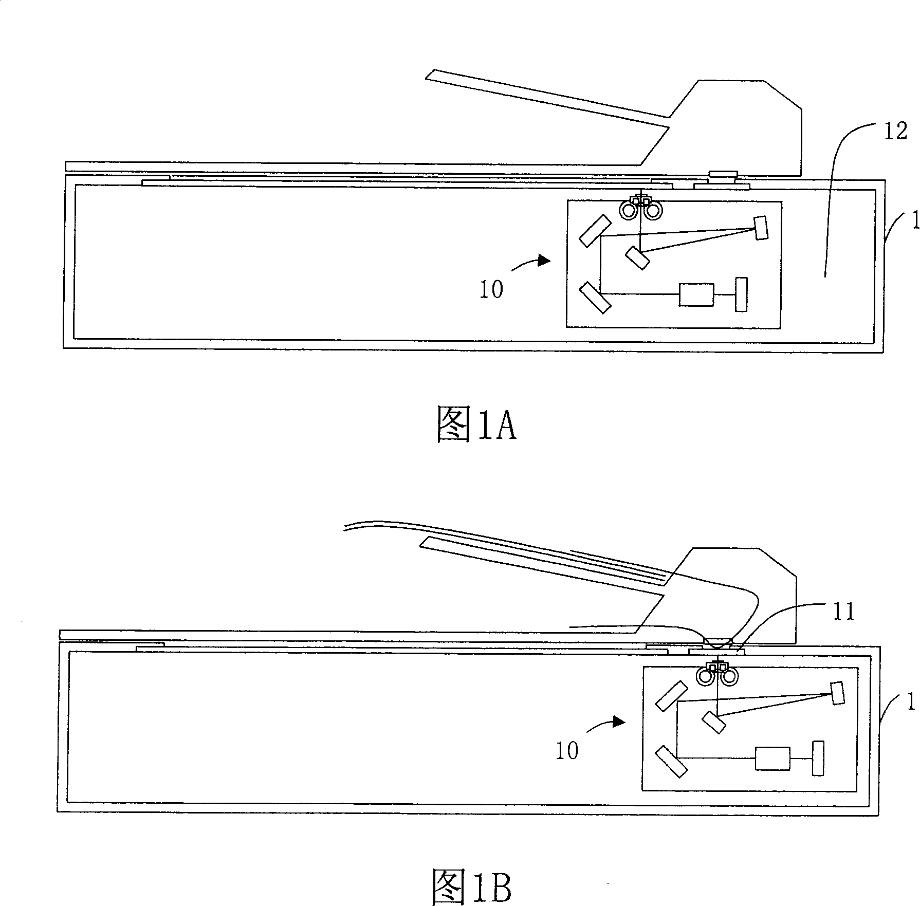
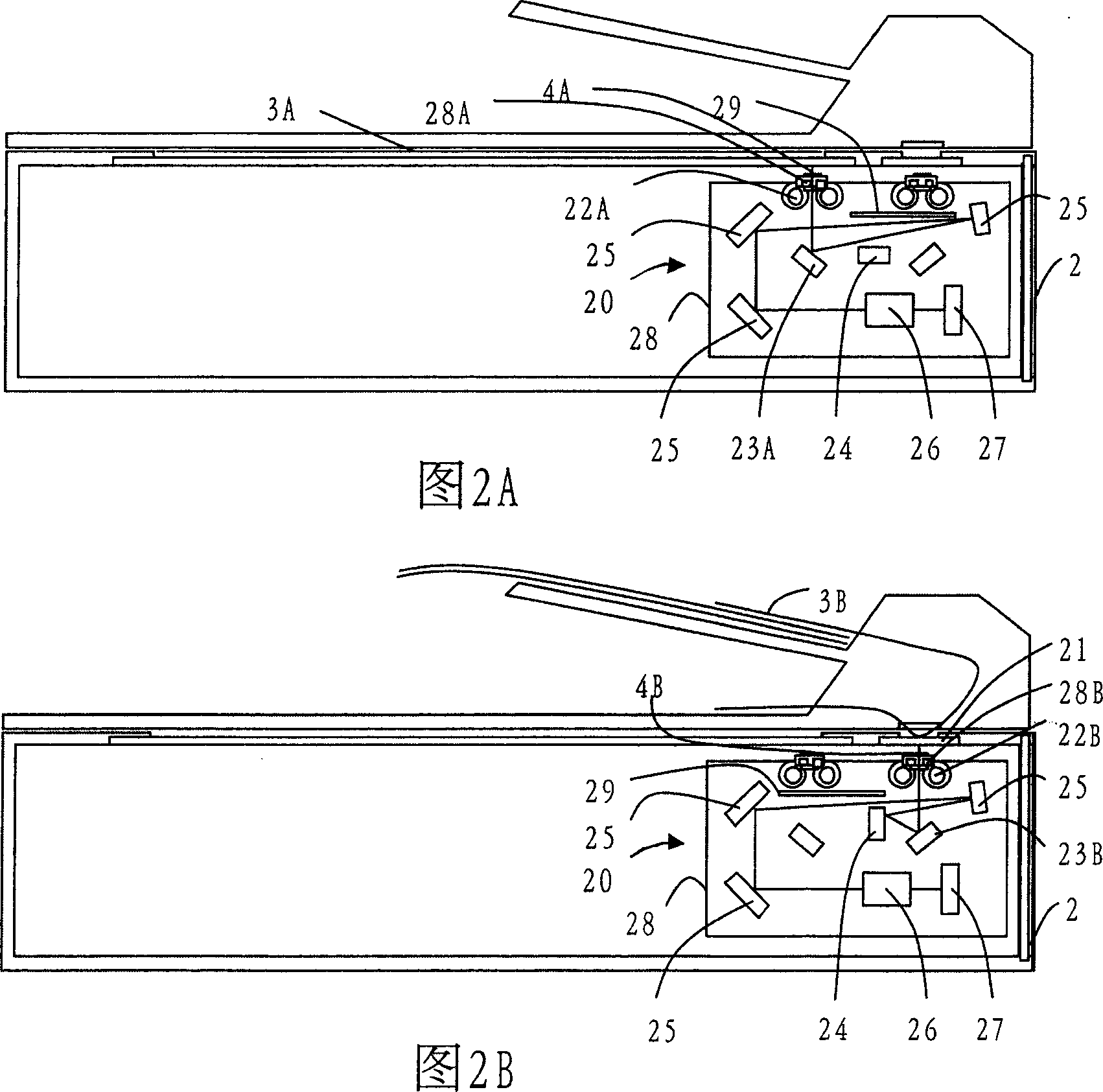
[0013] According to a preferred embodiment of the present invention, a movement structure suitable for scanners is provided, and the light path switching and the configuration schematic diagram of each optical component of the movement structure during platform scanning and paper-fed scanning can be shown as follows: Referring to FIG. 2A and FIG. 2B .

[0014] 2A and 2B, the movement structure 20 applied in the scanner 2 provided by this embodiment includes light sources 22A and 22B, lenses 23A and 23B, movable lenses 24, lens groups 25, lenses 26, photosensitive Measuring assembly 27 and housing 28 for accommodating the above-mentioned optical assemblies. Wherein, two slots 28A and 28B are formed on the casing 28, and two light sources 22A and 22B are correspondingly arranged beside the two slots 28A and 28B, so that when the scanner 2 is shown in FIG. 2A When performing flatbed scanning or paper-fed scanning as shown in FIG. 2B , the light source 22A or 22B can irradiate th...


PUM


Abstract

This invention provides one scanner center structure, which comprises the following parts: shell set with first and second open tanks and with first light source into first tank and second light source to the second tank inside; first lens down the first tank and second lens down second tank; active lens; lens set; lens probe and light sensor elements. This invention can realize switching light path design through double light sources.

Description

technical field [0001] The invention relates to a movement structure of a scanner, in particular to a movement structure with dual light sources and switchable light paths. Background technique [0002] When a user is scanning a large number of manuscripts, a flatbed scanner that can only scan one manuscript at a time cannot meet the needs of the user. Therefore, a scanner that can be matched with an automatic document feeder (ADF) to perform flatbed scanning as shown in FIG. 1A and also perform sheet-feeding scanning as shown in FIG. 1B has become a mainstream scanner at present. [0003] Continue to refer to Fig. 1A and Fig. 1B, but the common scanner 1 still adopts the same movement structure 10 as the flatbed scanner, so when it is necessary to perform paper-fed scanning, the movement structure 10 must be completely moved to Scanning can only be performed under the scanning window 11. Unavoidably, some placement space 12 must be reserved in the scanner 1 to place the mo...

Claims


Application Information

Patent Timeline
IPC IPC(8): H04N1/024
Inventor 蔡益元张有诚
Owner PRIMAX ELECTRONICS LTD
Features
  • R&D
  • Intellectual Property
  • Life Sciences
  • Materials
  • Tech Scout
  • Unparalleled Data Quality
  • Higher Quality Content
  • 60% Fewer Hallucinations
Learn More