Optical transmission module

a technology of optical transmission module and optical transmission element, which is applied in the direction of optical elements, semiconductor lasers, instruments, etc., can solve the problems of difficult control of the intensity of light emitted, inability of light-receiving elements to obtain precise monitoring, etc., and achieve the effect of more constan

Active Publication Date: 2018-06-19
LUMENTUM JAPAN INC
View PDF40 Cites 1 Cited by
  • Summary
  • Abstract
  • Description
  • Claims
  • Application Information

AI Technical Summary

Benefits of technology

[0010]It is an object of the invention to provide an optical transmission module provided with a plurality of light-emitting elements and a plurality of light-receiving elements, in which each of the plurality of light-receiving elements accurately monitors light emitted from the light-emitting element, and thus the intensities of the lights emitted from the plurality of light-emitting elements are controlled so as to be more constant.

Problems solved by technology

When the leakage light or the like described above is incident on the light-receiving element, the light-receiving element cannot obtain a precise monitoring result.
As a result, it may become difficult to control the intensity of the light emitted from the one light-emitting element so as to be constant.

Method used


Image

  • Optical transmission module
  • Optical transmission module
  • Optical transmission module

Examples


first embodiment

[0020]First, an outline of an optical transmission module according to a first embodiment of the invention will be described with reference to FIGS. 1 and 2.

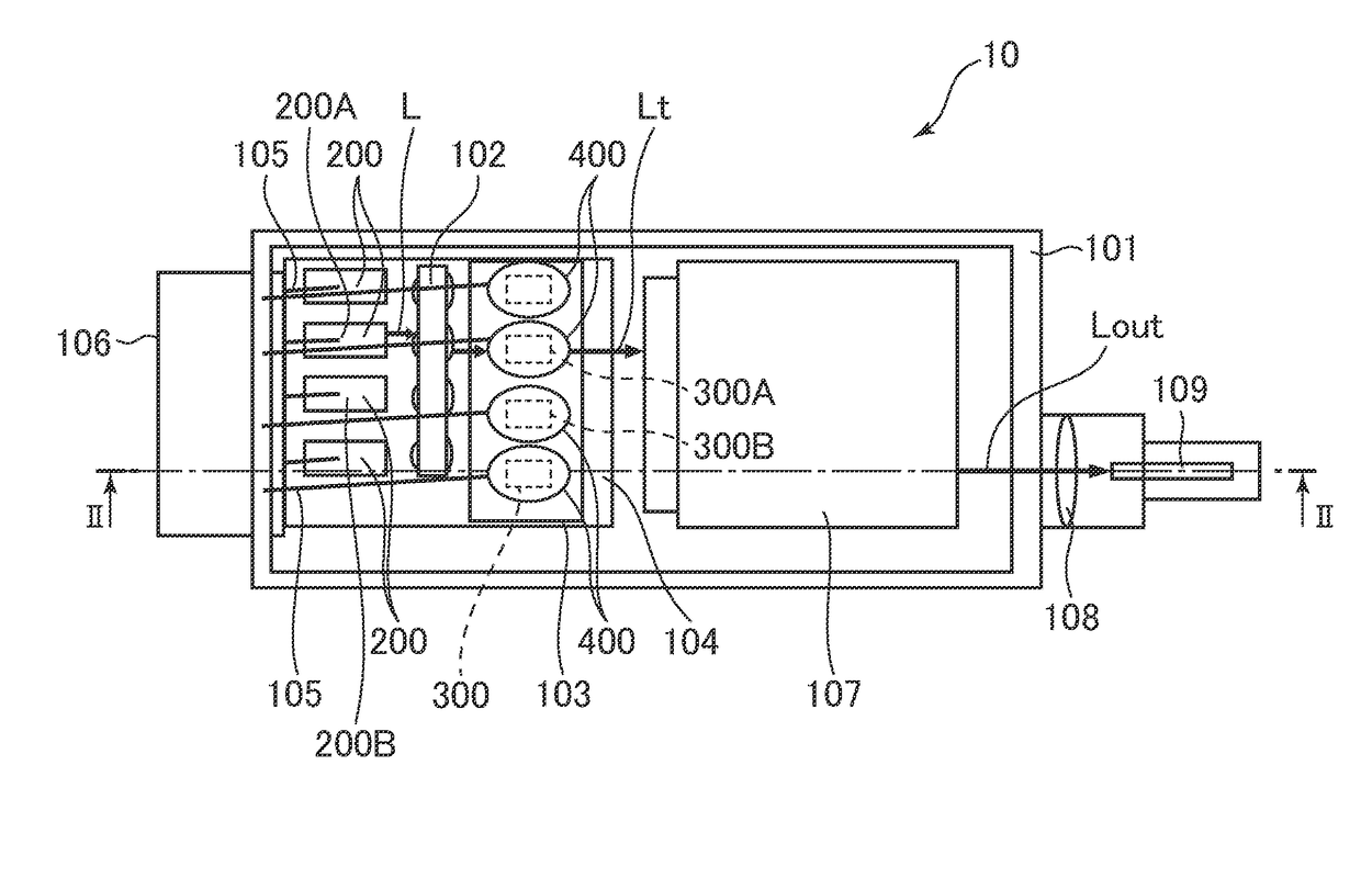
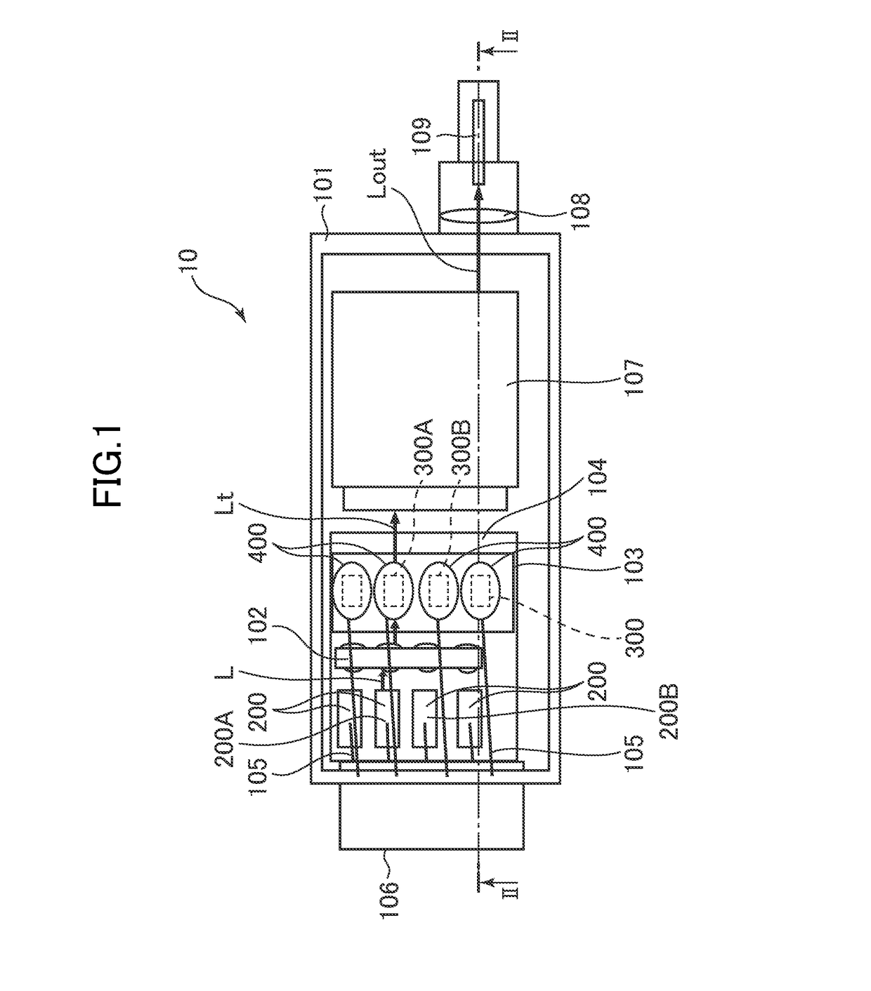
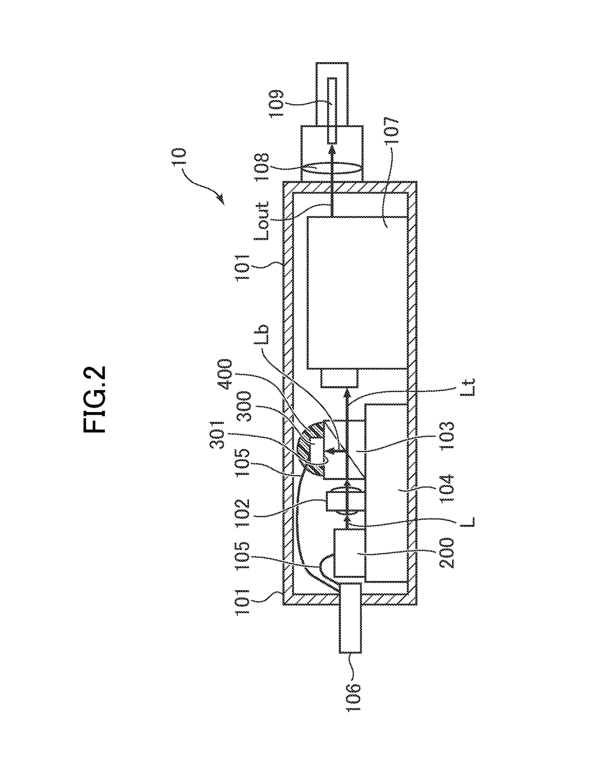
[0021]FIG. 1 is a diagram showing the state of the interior of the optical transmission module according to the first embodiment of the invention, viewed from above. Moreover, FIG. 2 is a diagram showing a cross-section along the section line II-II in FIG. 1, showing the configuration of the optical transmission module according to the first embodiment.

[0022]The optical transmission module 10 according to the first embodiment is an optical transmission module 10 that converts an electric signal to an optical signal and outputs the optical signal. The optical transmission module 10 includes: a package 101; a plurality of light-emitting elements 200 each emitting light by space transmission in the interior of the package 101; a repeater 107 for guiding a portion of the light in the interior of the package 101 and transmitting the ...

second embodiment

[0053]Hereinafter, an outline of an optical transmission module 20 according to a second embodiment of the invention will be described with reference to FIGS. 3 and 4. Configurations having the same functions as those of the optical transmission module 10 according to the first embodiment in FIGS. 1 and 2 are denoted by the same reference numerals and signs in FIGS. 3 and 4.

[0054]FIG. 3 is a diagram showing the state of the interior of the optical transmission module according to the second embodiment of the invention, viewed from above. FIG. 4 is a diagram showing a cross-section along the section line IV-IV in FIG. 3, showing the configuration of the optical transmission module according to the second embodiment.

[0055]The optical transmission module 20 according to the second embodiment is different from the optical transmission module 10 according to the first embodiment described above in that the beam splitter 103 is not included. In association with the difference, the install...


PUM


Abstract

An optical transmission module that converts an electric signal to an optical signal and outputs the optical signal, including: a package; a plurality of light-emitting elements each emitting light in the interior of the package; a plurality of light-receiving elements each including a light-receiving surface on which a portion of the light is incident in the interior of the package, for monitoring light outputs of the plurality of light-emitting elements; and light-shielding members provided on the plurality of light-receiving elements while avoiding the light-receiving surfaces.

Description

CROSS-REFERENCE TO RELATED APPLICATION[0001]The present application claims priority from Japanese application JP2015-057797 filed on Mar. 20, 2015, the content of which is hereby incorporated by reference into this application.BACKGROUND OF THE INVENTION[0002]1. Field of the Invention[0003]The present invention relates to an optical transmission module.[0004]2. Description of the Related Art[0005]JP2005-019746 A discloses a semiconductor laser device including a light-emitting element and a light-receiving element disposed in an accommodating portion, in which signal light from the light-emitting element is emitted through a transparent portion formed in a wall surface of the accommodating portion. The semiconductor laser device includes a scattered-light-shielding member for blocking scattered light, caused by the reflection of the signal light emitted through the transparent portion from the light-emitting element at the transparent portion, from being incident on the light-receiv...

Claims


Application Information

Patent Timeline
Patent Type & Authority Patents(United States)
IPC IPC(8): H04B10/00G02B6/00G02B6/36H01S5/0683H01S5/022
CPCG02B6/00H01S5/02284H01L2224/48091H01L2224/8592H01S5/0222H01S5/02228H01S5/0683H01S5/02216H01L2924/00014G02B6/4286G02B6/4204G02B6/4296H01S5/02234H01S5/02251
Inventor HASEGAWA, TAKAYUKIMURAKAMI, DAISUKEYAMASHITA, TAKESHI
Owner LUMENTUM JAPAN INC
Why Eureka
Try Eureka