Lock for a flap or door

Active Publication Date: 2018-07-03
KIEKERT & KOMMANDITGES
View PDF30 Cites 2 Cited by
  • Summary
  • Abstract
  • Description
  • Claims
  • Application Information

AI Technical Summary

Benefits of technology

[0042]In one embodiment of the invention the release lever can move a blocking lever of the locking mechanism out of its blocking position. For this purpose, generally a relatively low force suffices. Where the pawl is subsequently moved out of its detent position by an opening moment initiated in the pawl by the rotary latch, the overall force required for opening the locking mechanism is advantageously very low.
[0043]One embodiment provides a spring for moving the blocking lever into its blocking position. The blocking lever can thus be simply and reliably moved into its blocking position by the spring. In one embodiment the blocking lever and pawl are designed in such a way that by moving the blocking lever in its blocking position the pawl is also moved into its detent position. The number of required parts is thus reduced further. At the same time both the weight and required space are also reduced.
[0044]In one embodiment, the release lever contains three lever arms. Using a first lever arm, a blocking lever is, in particular, moved out of its blo

Problems solved by technology

Locking surfaces refers to surfaces on the pawl and rotary latch abutting to ensure locking of the locking mechanism and that result in overlapping.
Where the rod assembly or the Bowden cable wear out due to ageing, this can also

Method used


Image

  • Lock for a flap or door
  • Lock for a flap or door
  • Lock for a flap or door

Examples


Embodiment Construction

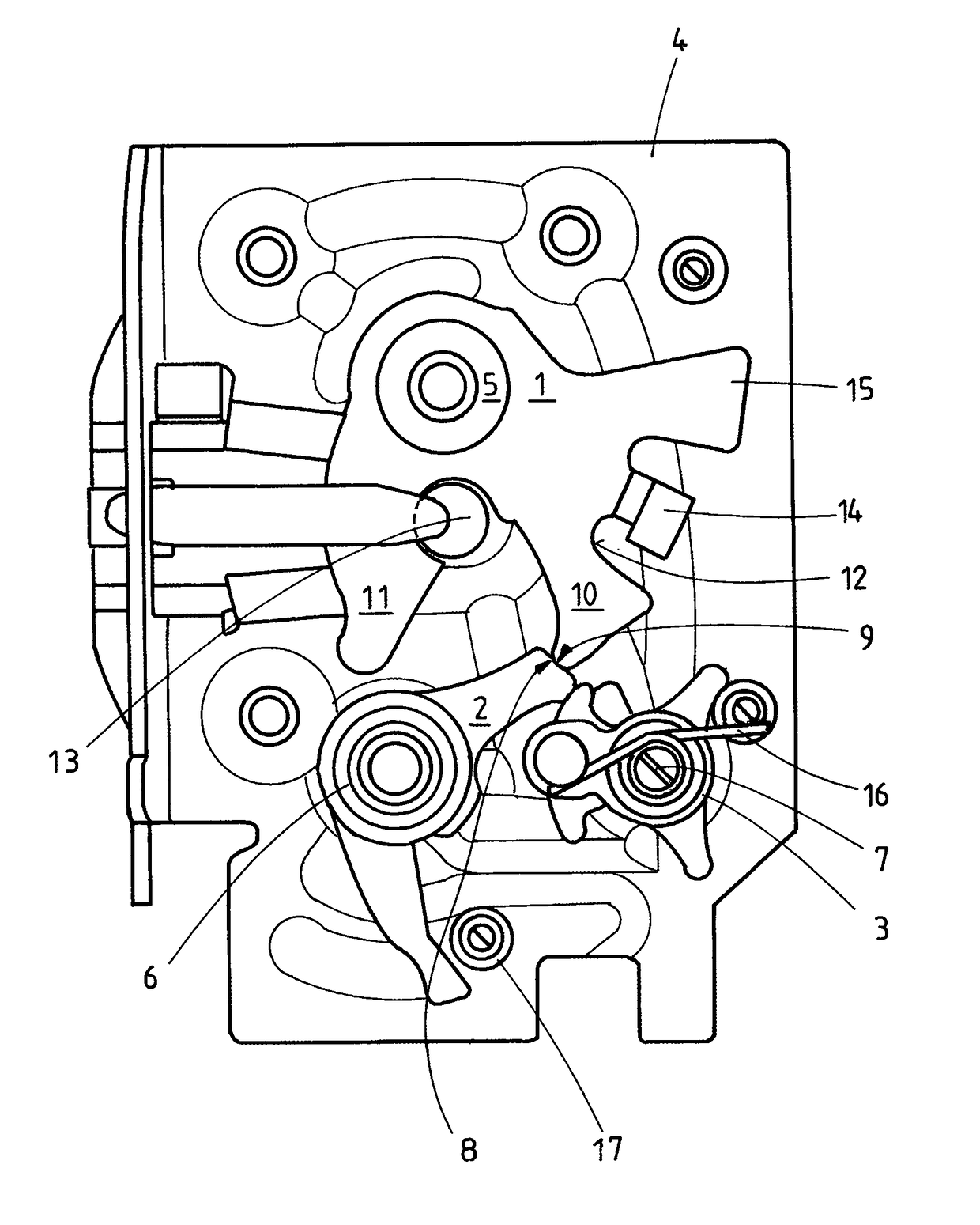
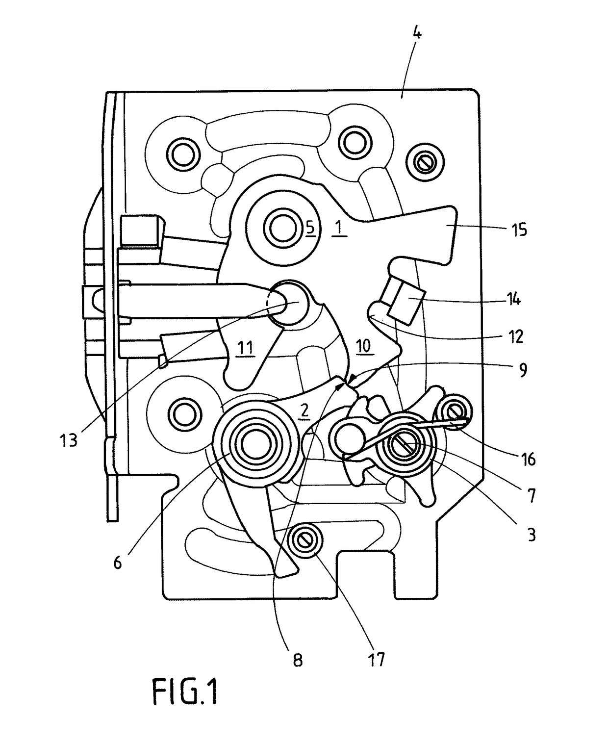
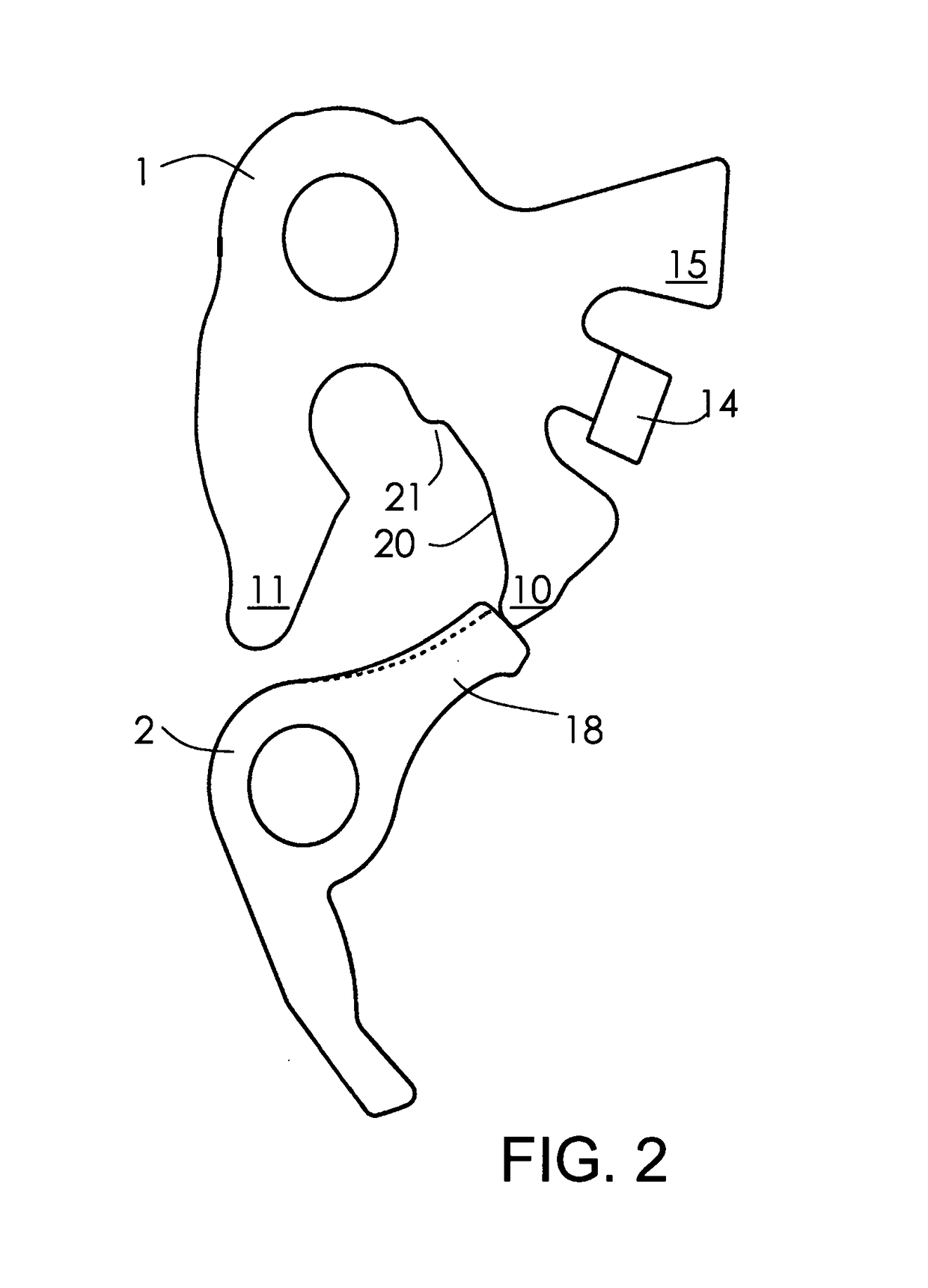
[0059]FIG. 1 shows a locking mechanism of a lock of a motor vehicle, comprising a rotary latch, a pawl 2 and a blocking lever 3 that are rotatably mounted on a lock case 4. The rotary latch 1 can be pivoted around its axis 5. The pawl 2 can be pivoted around its axis 6. The blocking lever 3 can be pivoted around its axis 7.

[0060]It must be noted that the invention is explained with reference to a lock consisting of several pawls, a so-called multiple pawl locking mechanism. The invention does, however, expressly not only relate to a multiple pawl locking mechanisms but is also applicable to all other locks with a locking mechanism.

[0061]Using its locking surface 8, the pawl 2 locks the rotary latch 1, resting with the locking surface 9 of its collecting arms 10 on the locking surface 8 of the pawl. In the example, an arrangement of the locking surface 8, 9 to each other has been chosen that ensures that the rotary latch 1 initiates an opening moment in the pawl 2. As a result of the...


PUM


Abstract

The invention relates to a door lock or flap lock comprising a locking mechanism that consists of a latch (1) and at least one pawl (2) for locking the latch (1). The locking surface of the pawl is so narrow that even slight pivoting movements are sufficient to unlock a locked locking mechanism, thus allowing for a reduction in volume and weight.

Description

[0001]This application is a national phase of International Application No. PCT / DE2013 / 000243 filed May 2, 2013 and published in the English language, which claims priority to German Patent Application No. DE 10 2012 207 440.6 filed May 4, 2012, which are all hereby incorporated herein by reference in their entirety.FIELD OF THE INVENTION[0002]The invention relates to a lock for a flap or a door. An exemplary lock is disclosed in publication DE 10 2008 061 524 A1. The door or flap can be a door or flap of a motor vehicle or of a building.BACKGROUND OF THE INVENTION[0003]The aforementioned lock comprises a locking mechanism that contains a rotary latch and at least one pawl with which the rotary latch can be locked in a closed position by locking surfaces of the pawl and rotary latch. Locking surfaces refers to surfaces on the pawl and rotary latch abutting to ensure locking of the locking mechanism and that result in overlapping. In a closed position the rotary latch can keep a door...

Claims


Application Information

Patent Timeline
IPC IPC(8): E05C3/16E05B85/26E05B77/04E05B17/00E05B85/20
CPCE05B85/20E05B17/0062E05B85/26E05B77/04Y10T292/1075E05B85/24
Inventor SCHOLZ, MICHAELHANDKE, ARMINHERRMANN, MICHAELBARTH, KARSTEN
Owner KIEKERT & KOMMANDITGES
Why Eureka
Try Eureka