Spin-orbit torque based magnetic recording

a magnetic recording and spin-orbit torque technology, applied in the direction of magnetic recording, data recording, instruments, etc., can solve the problems of difficult pseudo-spin-valve structure and lower energy efficiency

Active Publication Date: 2018-07-03
WESTERN DIGITAL TECH INC
View PDF17 Cites 50 Cited by
  • Summary
  • Abstract
  • Description
  • Claims
  • Application Information

AI Technical Summary

Problems solved by technology

The pseudo spin-valve structure is difficult to make, and high switching current and voltage (Vjump) are utilized during its operation, leading to a lower level of energy efficiency.

Method used


Image

  • Spin-orbit torque based magnetic recording
  • Spin-orbit torque based magnetic recording
  • Spin-orbit torque based magnetic recording

Examples


Embodiment Construction

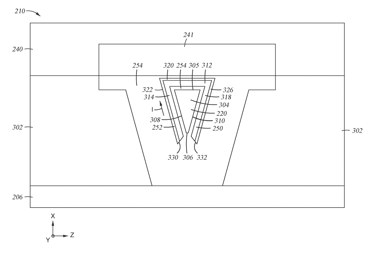
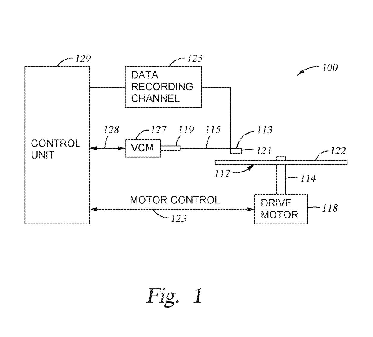
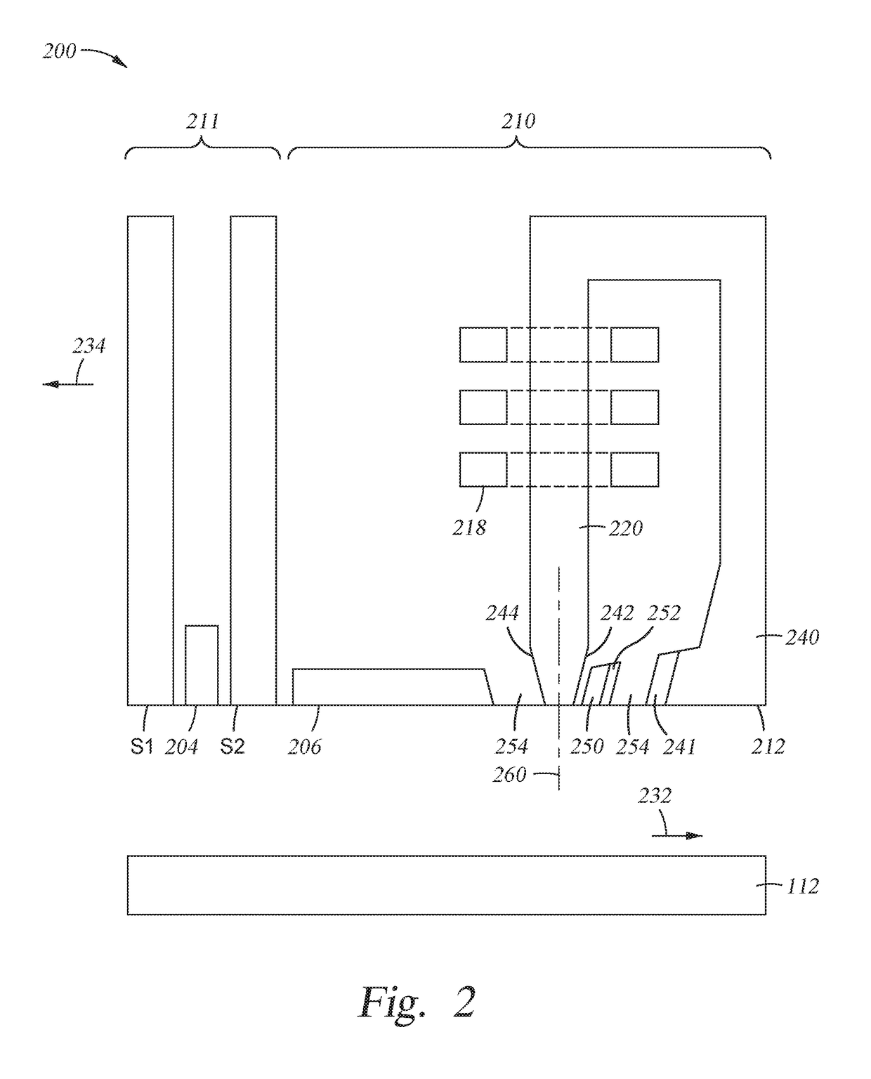
[0019]The present disclosure generally relates to data storage devices, and more specifically, to a magnetic media drive employing a magnetic recording head. The head includes a main pole, a spin-torque structure surrounding at least a portion of the main pole at a MFS, and a spin Hall structure surrounding the spin-torque structure. Strong SOT is generated from the spin Hall structure, enforcing in-plane magnetization oscillation in the spin-torque structure. The SOT based head with the spin Hall structure surrounding the spin-torque structure utilizes less current flowed to the spin Hall structure due to the strong SOT generated by the spin Hall structure.

[0020]The terms “over,”“under,”“between,” and “on” as used herein refer to a relative position of one layer with respect to other layers. As such, for example, one layer disposed over or under another layer may be directly in contact with the other layer or may have one or more intervening layers. Moreover, one layer disposed bet...


PUM

PropertyMeasurementUnit
thicknessaaaaaaaaaa
spin-torqueaaaaaaaaaa
insulatingaaaaaaaaaa

Abstract

The present disclosure generally relates to data storage devices, and more specifically, to a magnetic media drive employing a magnetic recording head. The head includes a main pole, a spin-torque structure surrounding at least a portion of the main pole at a media facing surface (MFS), and a spin Hall structure surrounding the spin-torque structure. Strong spin-orbit torque (SOT) is generated from the spin Hall structure, enforcing in-plane magnetization oscillation in the spin-torque structure. The SOT based head with the spin Hall structure surrounding the spin-torque structure utilizes less current flowed to the spin Hall structure due to the strong SOT generated by the spin Hall structure.

Description

BACKGROUNDField of the Disclosure[0001]Embodiments of the present disclosure generally relate to data storage devices, and more specifically, to a magnetic media drive employing a magnetic recording head.Description of the Related Art[0002]Over the past few years, various magnetic recording methods have been studied to improve the areal density of a magnetic media device, such as a hard disk drive (HDD). For example, microwave assisted magnetic recording (MAMR) utilizes spin-transfer torque (STT), which is generated from a pseudo spin-valve structure. During operation, electrical current flows from the main pole to the trailing shield hot seed layer, and the spin-torque layer magnetization switching (or precession) is induced by the STT.[0003]The pseudo spin-valve structure is difficult to make, and high switching current and voltage (Vjump) are utilized during its operation, leading to a lower level of energy efficiency.[0004]Therefore, there is a need in the art for an improved da...

Claims


Application Information

Patent Timeline
Patent Type & Authority Patents(United States)
IPC IPC(8): G11B5/31G11B5/127
CPCG11B5/1278G11B5/3133G11B5/315G11B5/02G11B5/235G11B5/3146G11B2005/0024
Inventor SONG, SUPINGLI, ZHANJIEHO, MICHAEL KUOK SAN
Owner WESTERN DIGITAL TECH INC
Why Eureka
Try Eureka