
Magnetic storage unit and data writing method thereof

A magnetic storage and data writing technology, applied in the field of non-volatile storage and logic, can solve the problems of limited application prospects, barrier breakdown, high current, etc., and achieve the effect of simplifying the control module

Inactive Publication Date: 2019-04-16
BEIHANG UNIV
View PDF5 Cites 13 Cited by
  • Summary
  • Abstract
  • Description
  • Claims
  • Application Information

AI Technical Summary

Problems solved by technology

[0004] Early MRAM uses a magnetic field to write data, but the required current is high and cannot be reduced with the reduction of the size of the magnetic tunnel junction, so the application prospect is limited
The second-generation MRAM uses current-induced spin transfer torque (Spintransfer torque, STT) to implement data writing, which solves the disadvantages of the above-mentioned magnetic field writing method, but the writing process of STT-MRAM needs to experience incubation delay (Incubation delay) , which severely restricts the writing speed, and both the writing current and the reading current pass directly through the magnetic tunnel junction, which can easily cause problems such as read disturbance (Read disturbance) and barrier breakdown (Barrier breakdown)
However, in order to achieve deterministic flipping of the PMA-MTJ state using SOT, it is generally necessary to apply an additional magnetic field to artificially break the symmetry of the system
However, the use of a magnetic field will complicate the design of the MRAM circuit, causing additional area and power overhead

Method used


Image

  • Magnetic storage unit and data writing method thereof
  • Magnetic storage unit and data writing method thereof
  • Magnetic storage unit and data writing method thereof

Examples


Embodiment Construction

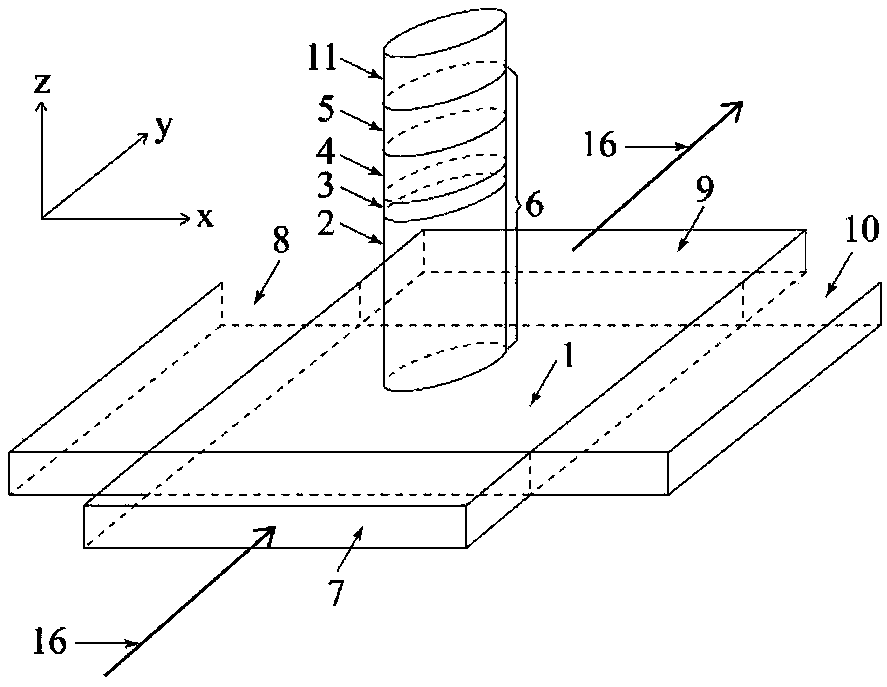
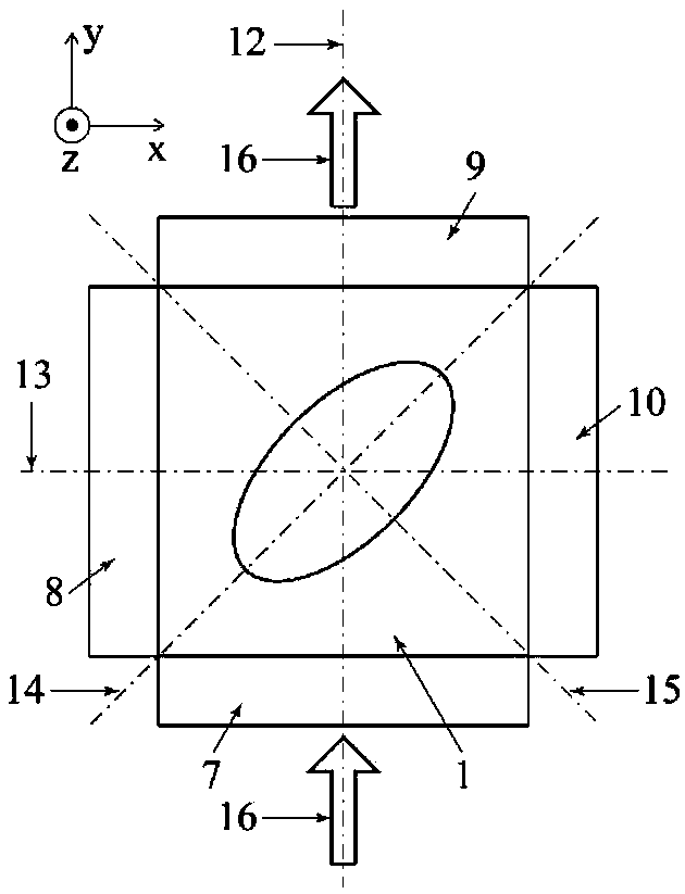
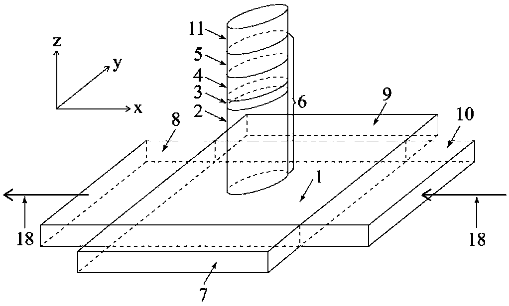
[0068] The substantive features of the present invention are further described with reference to the accompanying drawings. The drawings are all schematic diagrams, and the thicknesses of the various functional layers or regions involved are not actual dimensions, and the resistance values, current values ​​and time delay values ​​in the working mode are also not actual values.

[0069] Detailed exemplary embodiments are disclosed herein, specific structural and functional details are merely representative for purposes of describing exemplary embodiments, therefore, the invention may be embodied in many alternative forms and should not be construed as It is to be construed as being limited only to the exemplary embodiments set forth herein, but to cover all changes, equivalents, and alternatives falling within the scope of the invention.

[0070] The invention proposes a magnetic storage unit and a data writing method thereof, which can be used not only for constructing a magn...


PUM


Abstract

The invention discloses a magnetic storage unit and a data writing method thereof, a magnetic tunnel junction with vertical magnetic anisotropy is manufactured above a strong spin orbit coupling layer, and four ports of the strong spin orbit coupling layer are respectively plated with an electrode. The surface of the magnetic tunnel junction is made into a shape with unequal long and short axes, the long axis of the shape of the surface of the magnetic tunnel junction and the longitudinal axis of the strong spin orbit coupling layer are not overlapped with each other, are not perpendicular toeach other, but are inclined with each other, and the inclined included angle is not equal to 0 degree and not equal to 90 degrees, but is between 0 degree and 90 degrees. In order to realize data writing operation by using spin orbit torque, current needs to be applied to the strong spin orbit coupling layer, and the path of the current can be divided into two choices along the longitudinal axisor the transverse axis of the strong spin orbit coupling layer. The final resistance state of the magnetic tunnel junction only depends on the path of the applied current and is independent of the positive and negative directions of the current. The data writing method does not need a magnetic field and has the advantages of high speed and low power consumption.

Description

【Technical field】 [0001] The invention relates to a magnetic storage unit and a data writing method thereof, belonging to the technical field of nonvolatile storage and logic. 【Background technique】 [0002] The current main performance bottlenecks faced by memory and logic computing units based on traditional semiconductor processes include two aspects: First, transistor leakage current continues to rise as feature sizes shrink, making static power consumption an increasing proportion of total system power consumption Secondly, in a typical computing architecture, the access speeds between various types of memory and between memory and logical computing units are seriously mismatched, which greatly reduces the data processing bandwidth. The emerging magnetic random access memory (MRAM) has the advantages of non-volatility, low power consumption, high speed, and almost unlimited rewritability. It is expected to become the next generation of general-purpose memory, and then s...

Claims


Application Information

Patent Timeline
IPC IPC(8): G11C11/409
CPCG11C11/409
Inventor 王昭昊赵巍胜朱道乾
Owner BEIHANG UNIV
Learn More