Spin current magnetization rotational element, spin-orbit-torque magnetoresistance effect element, magnetic memory, and high-frequency magnetic element

a spin current magnetization and rotational element technology, applied in the direction of magnetic bodies, instruments, substrate/intermediate layers, etc., can solve the problems of difficult control of oxygen content, deterioration of the degree of integration of the integrated circuit including the insufficient elucidation of the mechanism, etc., to achieve excellent spin current magnetization rotational element, increase the effect of electricity consumption and no deterioration of the degree of integration

Active Publication Date: 2019-03-07
TDK CORPARATION
View PDF0 Cites 12 Cited by
  • Summary
  • Abstract
  • Description
  • Claims
  • Application Information

AI Technical Summary

Benefits of technology

[0011]The present disclosure has been made in consideration of the foregoing problems, and an object thereof is to provide a spin current magnetization rotational element which is configured to be able to induce a magnetization rotation without causing an increase in consumption of electricity and a spin current magnetization rotational element which does not cause deterioration in degree of integration.
[0013]As a result of intensive investigation, the inventors have found that when a magnetic field applying part, which generates a regular magnetic field even if a current or the like does not flow, is embedded in an element, a magnetization rotation can be easily caused by utilizing a spin-orbit torque (SOT) without deterioration in integration properties being caused.
[0028]According to the spin current magnetization rotational element of the aspect described above, it is possible to provide a spin current magnetization rotational element which can perform a magnetization rotation without increasing consumption of electricity and deterioration in the degree of integration is not caused. In addition, it is possible to provide a magnetoresistance effect element, a magnetic memory, and a high-frequency magnetic element including such an excellent spin current magnetization rotational element.

Problems solved by technology

This mechanism has not been sufficiently elucidated.
A generation source for an external magnetic field provided separately outside leads to deterioration in the degree of integration of an integrated circuit including a spin current magnetization rotational element.
94 has a problem in that it is difficult to control the oxygen content.
Particularly, in each of elements simultaneously manufactured in a thin-film process, it is difficult to form oxygen content gradients similar to each other for the elements in mass production.
A rotation of an unintended magnetization becomes noise in data and hinders long-term storage of data.
However, when a structure assisting a magnetization rotation by utilizing a wiring is used, there is problem in that more electricity is consumed due to the wiring and the degree of integration of a circuit deteriorates in order to form the wiring.

Method used


Image

  • Spin current magnetization rotational element, spin-orbit-torque magnetoresistance effect element, magnetic memory, and high-frequency magnetic element
  • Spin current magnetization rotational element, spin-orbit-torque magnetoresistance effect element, magnetic memory, and high-frequency magnetic element
  • Spin current magnetization rotational element, spin-orbit-torque magnetoresistance effect element, magnetic memory, and high-frequency magnetic element

Examples


first embodiment

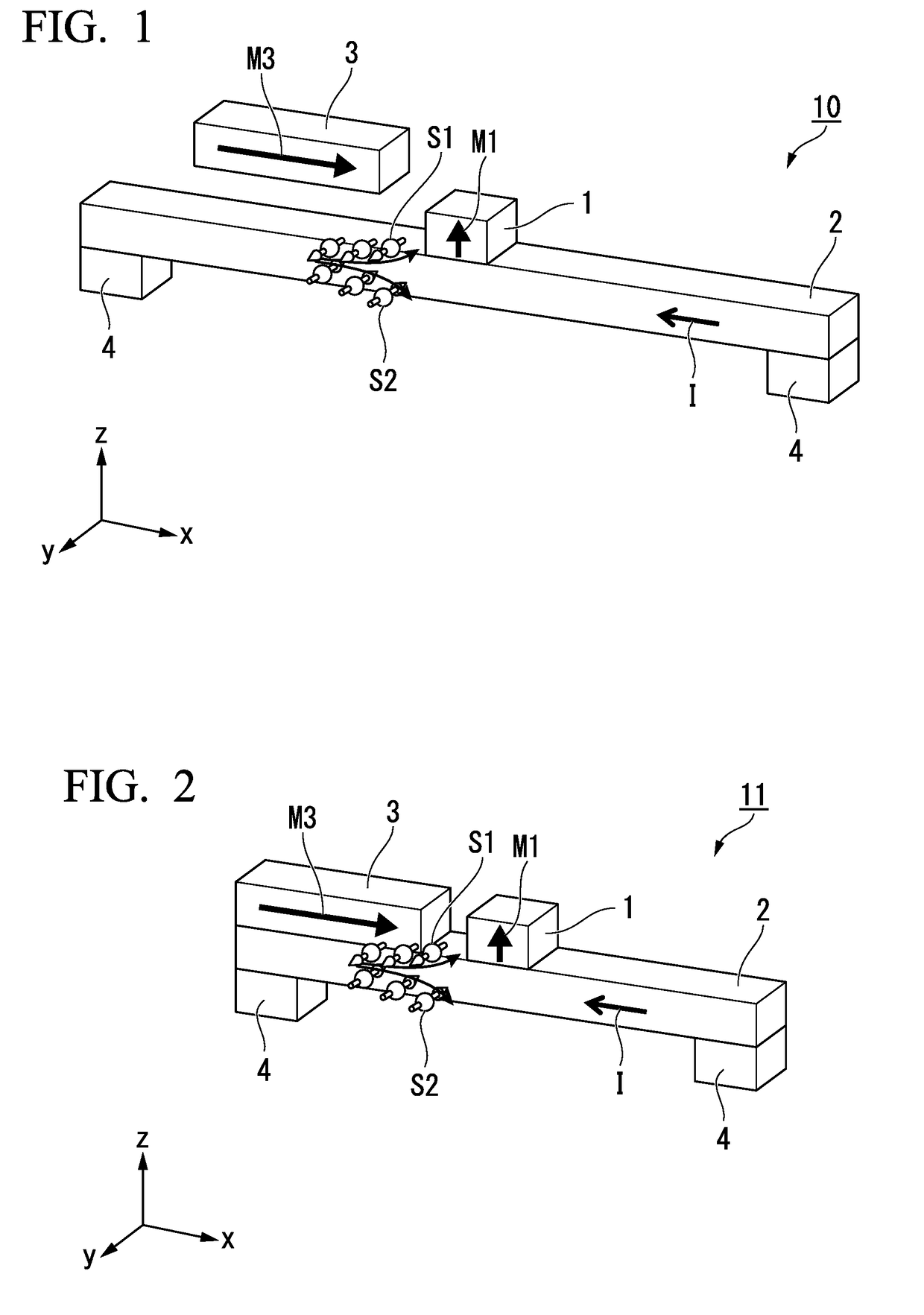
[0049]FIG. 1 is a perspective view schematically illustrating a spin current magnetization rotational element according to a first embodiment.

[0050]A spin current magnetization rotational element 10 according to the first embodiment has a first ferromagnetic layer 1, a spin-orbit torque wiring 2, a first magnetic field applying layer 3, and via wirings 4. In the spin current magnetization rotational element 10 illustrated in FIG. 1, the first ferromagnetic layer 1 having the same width as the spin-orbit torque wiring 2 and having a rectangular shape in a plan view is laminated in a middle part on an upper surface of the belt-shaped spin-orbit torque wiring 2. In addition, the first magnetic field applying layer 3 has a width and a length equal to those of the first ferromagnetic layer 1 in a plan view and is disposed to be separated from the first ferromagnetic layer 1 and the spin-orbit torque wiring 2.

[0051]Hereinafter, description will be given while defining a first direction in...

second embodiment

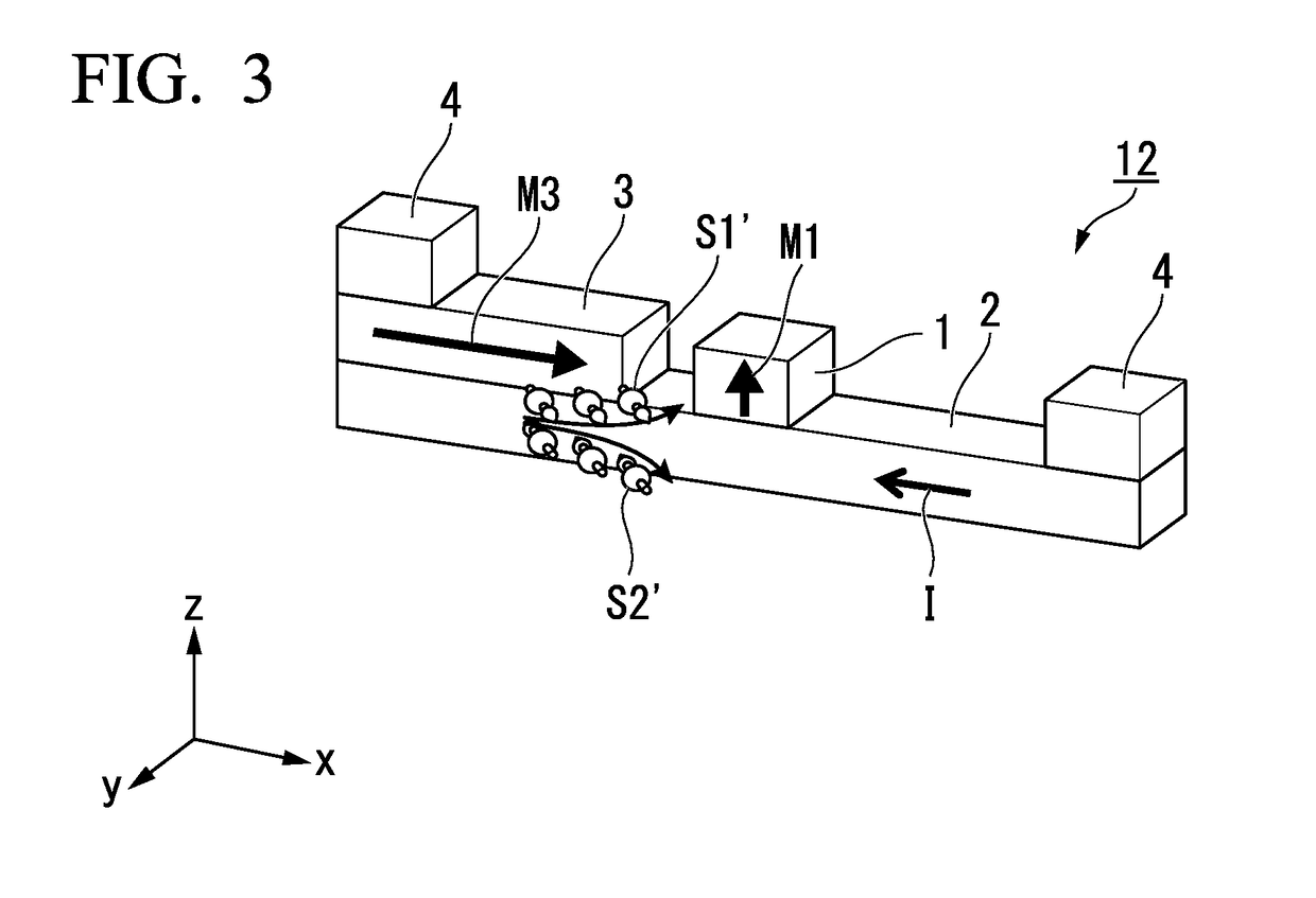
[0086]A spin current magnetization rotational element 11 according to the second embodiment illustrated in FIG. 2 is different from the spin current magnetization rotational element 10 according to the first embodiment in that the first magnetic field applying layer 3 and the spin-orbit torque wiring 2 are in contact with each other. Other configurations are the same as those of the spin current magnetization rotational element 10 according to the first embodiment. The same reference signs are applied to the same configurations, and description thereof is omitted.

[0087]The spin-orbit torque wiring 2 containing a heavy metal has high electric resistance. When the first magnetic field applying layer 3 is a metal, heat generation due to the current I can be minimized by connecting the first magnetic field applying layer 3 formed of a metal having low resistance to the spin-orbit torque wiring 2.

[0088]In addition, a magnetization rotation of the spin current magnetization rotational ele...

third embodiment

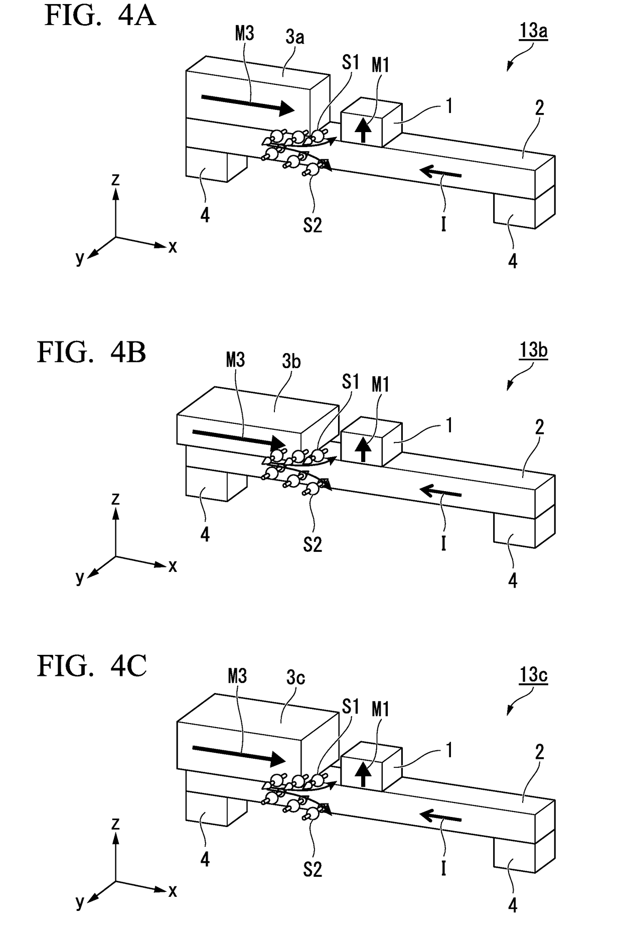
[0094]Spin current magnetization rotational elements 13a, 13b, and 13c according to a third embodiment illustrated in FIG. 4A to FIG. 4C are different from the spin current magnetization rotational element 11 according to the second embodiment in that a cross-sectional area of the first magnetic field applying layer 3 cut in a yz-plane is larger than a cross-sectional area of the first ferromagnetic layer 1 cut in the yz-plane. Other configurations are the same as the spin current magnetization rotational element 11 according to the second embodiment. The same reference signs are applied to the same configurations, and description thereof is omitted.

[0095]In the spin current magnetization rotational element 13a illustrated in FIG. 4A, the width of a first magnetic field applying layer 3a in the y-direction is equal to the width of the first ferromagnetic layer 1 in the y-direction, and the height thereof in the z-direction is higher than the height of the first ferromagnetic layer 1...


PUM

PropertyMeasurementUnit
atomic numberaaaaaaaaaa
spin diffusion lengthaaaaaaaaaa
magnetic fieldaaaaaaaaaa

Abstract

A spin current magnetization rotational element is provided in which deterioration in the degree of integration is prevented from being caused and a magnetization rotation can be easily realized. A spin current magnetization rotational element includes a spin-orbit torque wiring which extends in a first direction, a first ferromagnetic layer which is laminated in a second direction intersecting the first direction; and a first magnetic field applying layer which is disposed to be separated from the first ferromagnetic layer in the first direction and configured to apply an assistant magnetic field assisting a magnetization rotation of the first ferromagnetic layer to the first ferromagnetic layer.

Description

TECHNICAL FIELD[0001]The present disclosure relates to a spin current magnetization rotational element, a spin-orbit-torque magnetoresistance effect element, a magnetic memory, and a high-frequency magnetic element.[0002]Priority is claimed on Japanese Patent Application No. 2017-170369, filed on Sep. 5, 2017, and Japanese Patent Application No. 2018-110604, filed on Jun. 8, 2018, the contents of which are incorporated herein by reference.BACKGROUND ART[0003]A giant magnetoresistance (GMR) element constituted of a multilayer film having a ferromagnetic layer and a nonmagnetic layer, and a tunneling magnetoresistance (TMR) element using an insulating layer (tunnel barrier layer, barrier layer) as a nonmagnetic layer are known as a magnetoresistance effect element. Generally, a TMR element has high element resistance and a high magnetoresistance (MR) ratio compared to a GMR element. Therefore, the TMR element has attracted attention as an element for a magnetic sensor, a high-frequenc...

Claims


Application Information

Patent Timeline
Patent Type & Authority Applications(United States)
IPC IPC(8): H01F10/32H01L43/02H01L27/22G11C11/16H03H11/04
CPCH01F10/329H01L43/02H01L27/222G11C11/161H01F10/3254H01F10/3286H03H11/04H10B61/20H10N52/00H10N52/01H10N50/10G11C11/1675H10B61/00H10N50/80
Inventor ISHITANI, YUGOSASAKI, TOMOYUKI
Owner TDK CORPARATION
Why Eureka
Try Eureka