Magnetic memory

a technology of magnetic memory and memory layer, applied in the field of magnetic memory, can solve the problems of increasing the amount of current needed for mram overall, affecting the operation life of the element, and affecting etc., and achieve the effect of raising the thermal stability of the magnetoresistance effect elemen

Active Publication Date: 2018-05-03
TDK CORPARATION
View PDF0 Cites 12 Cited by
  • Summary
  • Abstract
  • Description
  • Claims
  • Application Information

AI Technical Summary

Benefits of technology

[0012]Additionally, when the current amount flowing through each TMR element or GMR element becomes large, the reversal current (leak current) increases, and a circuit configuration for preventing this leak current becomes necessary. As a result, the integration rate of the integrated circuit becomes lower.
[0013]The present invention was made in view of the above-mentioned problems, and has the purpose of providing a magnetic memory that can lower the reversal current and increase the integration density.
[0028]Based on the spin-orbit torque type magnetoresistance effect elements according to one embodiment of the present invention, it is possible to lower the reversal current and increase the integration density.

Problems solved by technology

However, if the current amount flowing through a single TMR element or GMR element is too large, the operating life of the element can be affected.
For example, the insulating layers of the TMR element may undergo insulation breakdown and the element may become incapable of recording data.
Additionally, if the current amount flowing through a single TMR element or GMR element becomes large, then the current amount necessary for the MRAM overall will also become large.

Method used


Image

  • Magnetic memory
  • Magnetic memory
  • Magnetic memory

Examples


first embodiment

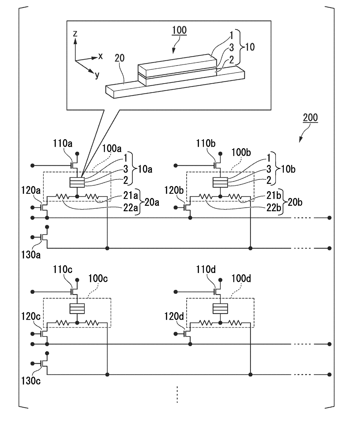
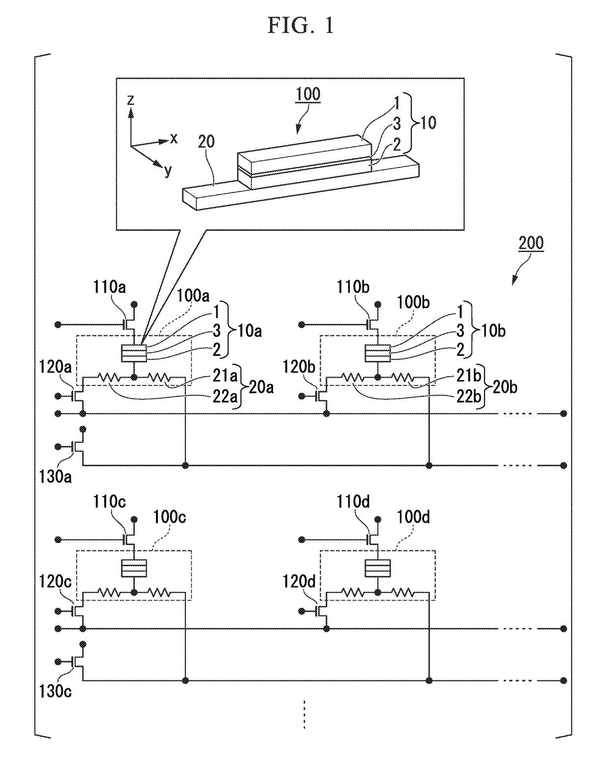
[0046]A circuit example of the magnetic memory 200 will be explained. The operating principles and the like of the spin-orbit torque type magnetoresistance effect element will be explained below.

[0047]FIG. 1 is a circuit diagram of an example of the magnetic memory 200 according to the first embodiment. In FIG. 1, the stacking direction of the magnetoresistance effect element 10 is defined as the z-direction, the first direction in which the spin-orbit torque wiring 20 extends is defined as the x-direction, and the second direction which is orthogonal to both the z-direction and the x-direction is defined as the y-direction.

[0048]The magnetic memory 200 illustrated in FIG. 1 comprises spin-orbit torque

[0049](SOT) type magnetoresistance effect elements 100 (100a, 100b, 100c, 100d ), read control elements 110 (110a, 110b, 110c, 110d; first control elements), element selection control elements 120 (120a, 120b, 120c, 120d; second control elements) and write control elements 130 (130a, 1...

second embodiment

[0138]In the first embodiment, an example in which the write control elements 130, when viewed as a matrix, are shared by a plurality of spin-orbit torque type magnetoresistance effect elements 100 that are arranged in the lateral direction, has been explained. In the present embodiment, an example in which the read control elements 110, when viewed as a matrix, are shared by a plurality of spin-orbit torque type magnetoresistance effect elements 100 that are arranged in the longitudinal direction, will be explained.

[0139]FIG. 7 is a circuit diagram of an example of a magnetic memory 200A according to the second embodiment. In FIG. 7, the stacking direction of the magnetoresistance effect element 10 is defined as the z-direction, the first direction in which the spin-orbit torque wiring 20 extends is defined as the x-direction, and the second direction which is orthogonal to both the z-direction and the x-direction is defined as the y-direction.

[0140]The magnetic memory 200A illustr...

third embodiment

[0199]An example in which a magnetic memory according to an embodiment is applied to a magnetic-field-assisted SOT-MRAM will be explained.

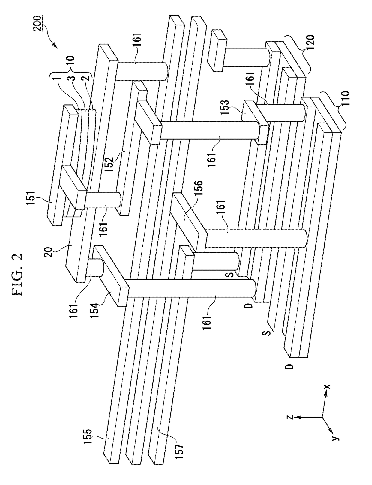
[0200]FIG. 9 is a perspective view of a modification example of a spin-orbit torque type magnetoresistance effect element 100, a write control element 130, an element selection control element 120, spin-orbit torque wiring 20 and magnetic-field-providing wiring 192 according to the third embodiment, when arranged three-dimensionally. In the present embodiment, the channels in the write control element 130 and the element selection control element 120 are oriented in the x-direction. The coordinate system is the same as that in FIG. 2. In FIG. 9, reference numbers 181 to 183 respectively denote wiring provided in each layer. Reference number 161 denotes a through-via that connects wiring to wiring. Reference number 191 denotes an insulating layer. Reference number 192 denotes magnetic-field-providing wiring for applying a magnetic field in a direct...


PUM


Abstract

A magnetic memory including a plurality of magnetoresistance effect elements that hold information, each including a first ferromagnetic metal layer with a fixed magnetization direction, a second ferromagnetic metal layer with a varying magnetization direction, and a non-magnetic layer sandwiched between the first and second ferromagnetic metal layers; a plurality of first control elements that control reading of the information, wherein each of the plurality of first ferromagnetic metal layers is connected to a first control element; a plurality of spin-orbit torque wiring lines that extend in a second direction intersecting with a first direction which is a stacking direction of the magnetoresistance effect elements, wherein each of the second ferromagnetic metal layers is joined to one spin-orbit torque wiring line; a plurality of second control elements that control electric current flowing through the spin-orbit torque wiring lines.

Description

BACKGROUND OF THE INVENTIONField of the Invention[0001]The present invention relates to a magnetic memory. Priority is claimed on Japanese Patent Application No. 2016-210535, filed Oct. 27, 2016, and Japanese Patent Application No. 2017-138387, filed Jul. 14, 2017, the contents of which are incorporated herein by reference.Description of Related Art[0002]Examples of known magnetoresistance effect elements include giant magnetoresistance (GMR) elements composed of a multilayer film of ferromagnetic layers and non-magnetic layers, and tunnel magnetoresistance (TMR) elements which use insulating layers (tunnel barrier layers, barrier layers) for the non-magnetic layers. Generally, TMR elements have a larger element resistance than GMR elements, but the magnetoresistance (MR) ratio is larger than GMR elements. Consequently, TMR elements are attracting much attention as elements for magnetic sensors, high-frequency components, magnetic heads and non-volatile random access memory (MRAM).[...

Claims


Application Information

Patent Timeline
Patent Type & Authority Applications(United States)
IPC IPC(8): H01L43/04H01L43/08H01L43/10H01L43/14G11C11/16
CPCH01L43/04H01L43/08H01L43/10H01L43/14G11C11/161G11C11/1673G11C11/1675G11C11/18G11C11/1659H10N50/85H10N50/10H10B61/22H10N52/80H10N52/01
Inventor SASAKI, TOMOYUKISHIOKAWA, YOHEITSUMITA, ATSUSHI
Owner TDK CORPARATION
Why Eureka
Try Eureka