De-icing splitter for an axial turbine engine compressor

a technology of axial turbine engine and splitter, which is applied in the direction of power plant arrangement/mounting, air transportation, jet propulsion plant, etc., can solve the problems of affecting efficiency, rotor blade damage, and block weight,

Active Publication Date: 2018-07-10
SAFRAN AERO BOOSTERS SA
View PDF9 Cites 6 Cited by
  • Summary
  • Abstract
  • Description
  • Claims
  • Application Information

AI Technical Summary

Benefits of technology

[0047]The present application simplifies the splitter while at the same time forming an antichamber for the hot gas. The number of components is reduced, and the shape of the shroud allows control over the flow thanks to the sizing of the notches. What happens is that their passage cross section limits the amount of flow passing through them. Moreover, this solution makes it possible to reduce mass because the exterior wall can remain of constant thickness above the upstream edge of the internal wall.
[0048]The arrangement makes the splitter economical. Specifically, the notches are shapes that are simple to achieve; over reduced lengths. When they are machined, the amount of material to be removed is limited. The zone in which they are cut is readily accessible and is of a stiffness suited to the cutting loadings involved. The effect of expansion on the bore section of the notches is lower. The arrangement makes it possible to maintain de-icing effectiveness that is independent of temperature, something that is of particular importance in the case of walls liable to frost.
[0049]The present architecture optimises operation because heating up can be achieved uniformly at all points. The thickness inside the external wall is compensated for by the grooves formed therein. Thus, the temperature of the supplied air can be reduced while at the same time maintaining safety.

Problems solved by technology

These blocks may also alter the geometry of the splitter and influence the stream of air entering the compressor, and this may impair the efficiency thereof.
As they develop, the blocks may become heavy and then break off as a result of turbine engine vibrations.
Carried along in the incoming stream, these blocks may be ingested by the compressor, with the risk of damaging the rotor blades on their way through.
However, such a splitter remains expensive because of the way in which the interfaces are arranged.
The geometry of the passages is complex, and this detracts from operation since the manufacturing tolerances impair the actual operating conditions.

Method used


Image

  • De-icing splitter for an axial turbine engine compressor
  • De-icing splitter for an axial turbine engine compressor
  • De-icing splitter for an axial turbine engine compressor

Examples


Embodiment Construction

[0015]The present application aims to solve at least one of the problems presented by the prior art. More specifically, it is an objective of the present application to simplify a de-icing splitter. The present application also aims is to make a splitter more lightweight.

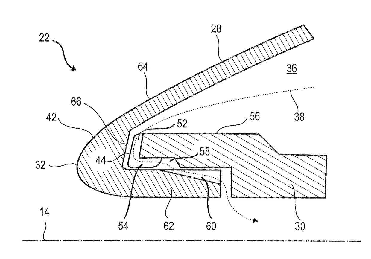
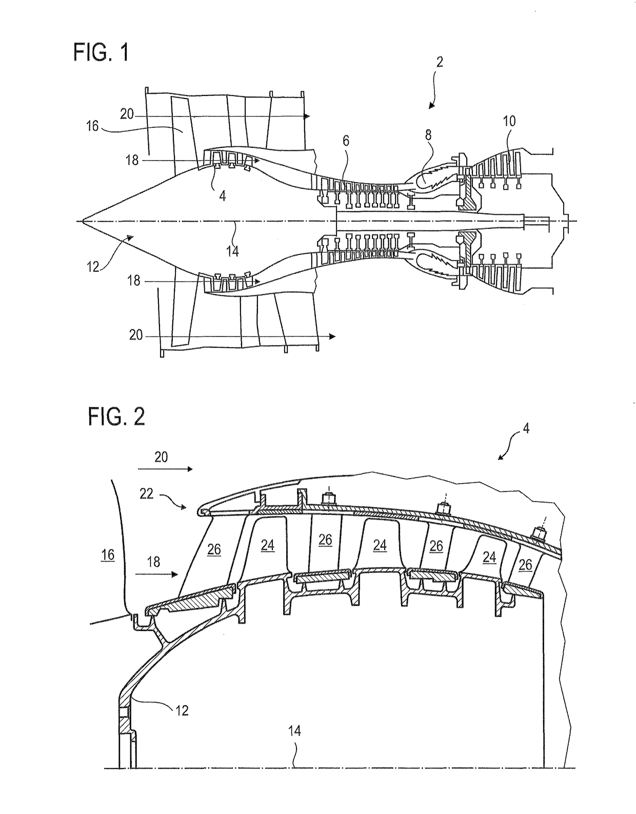
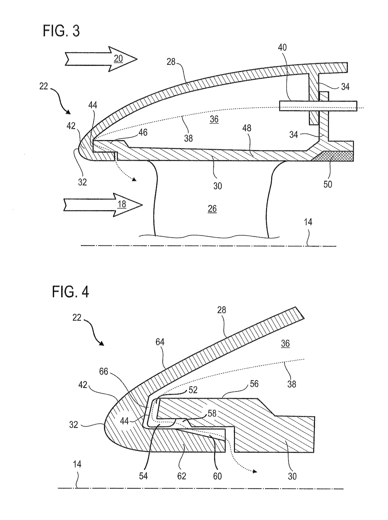
[0016]One subject of the present application is a splitter for an axial turbine engine, notably for a compressor of an axial turbine engine, the splitter comprising: an external annular wall; an internal annular wall with a circular upstream edge connected to the external wall, the internal wall being configured to delimit an internal annular stream separated by the splitter, notably a primary or main stream; notable in that the upstream edge of the internal wall comprises at least one notch which passes radially through the internal wall so as to allow de-icing fluid to circulate through the internal wall.

[0017]According to an advantageous embodiment of the present application, the internal wall comprises at least ...


PUM


Abstract

A de-icing and anti-icing splitter for an axial turbine engine low-pressure compressor has an external annular wall delimiting the secondary or bypass flow, and an internal annular wall; notably an external stator shroud; delimiting the primary or main stream. The upstream edge of the internal wall is fixed to the upstream annular hook of the external wall. The splitter has a series of notches which pass radially through the internal wall to allow de-icing fluid to circulate through the hook. The notches may form crescents. The splitter becomes simpler while at the same time maintaining optimal efficiency.

Description

[0001]This application claims priority under 35 U.S.C. § 119 to Belgium Patent Application No. 2015 / 5508, filed 13 Aug. 2015, “De-Icing Splitter for an Axial Turbine Engine Compressor,” which is incorporated herein by reference for all purposes.BACKGROUND[0002]1. Field of the Application[0003]The present application relates to a de-icing splitter for an axial turbine engine. More specifically, the present application relates to the de-icing of a splitter by reinjecting a hot gas into the splitter. The present application also relates to an axial turbine engine, notably to an aeroplane turbojet or to an aircraft turboprop engine.[0004]2. Description of Related Art[0005]An aeroplane multi-stream turboprop engine is designed to be environmentally friendly. With a view to optimizing thrust and efficiency, while at the same time reducing noise nuisance, a turboprop engine operates using several annular streams of air. To do that, the turboprop engine splits an incoming stream into a prim...

Claims


Application Information

Patent Timeline
Patent Type & Authority Patents(United States)
IPC IPC(8): F01D25/02B64D15/04F02C7/047B64D33/02
CPCB64D15/04B64D33/02F01D25/02F02C7/047Y02T50/671B64D2033/0233F05D2220/323F04D29/584Y02T50/60
Inventor BOUILLON, DAVIDCOLLIN, CLEMENTTERLINDEN, GUILLAUME
Owner SAFRAN AERO BOOSTERS SA
Why Eureka
Try Eureka