Air flow adjusting structure for vehicle

a technology for air flow and vehicle, which is applied in the direction of vehicle components, vehicle body streamlining, superstructure sub-units, etc., can solve problems such as complicated structure, and achieve the effect of desired strength

Active Publication Date: 2018-07-17
TOYOTA JIDOSHA KK
View PDF24 Cites 52 Cited by
  • Summary
  • Abstract
  • Description
  • Claims
  • Application Information

AI Technical Summary

Benefits of technology

[0007]The present disclosure provides a air flow adjusting structure for a vehicle to adjust air in a wheel house with a simple configuration.
[0012]According to the above aspect, it is possible to straighten the air introduced from the vehicle-front side into the air flow passage, and the air introduced from the vehicle-rear side into the air flow passage so as to be discharged in respective different directions by using the adjusting rib having such a simple configuration of projecting from the top of the arch in the vehicle-downward direction.
[0014]In the above aspect, the air introduced from the vehicle-front side into the air flow passage collides against the adjusting rib, flows in the vehicle-rearward direction, and is discharged inward in the vehicle-width direction. On the other hand, the air introduced from the vehicle-rear side into the air flow passage collides against the adjusting rib, flows in the vehicle-frontward direction, and is discharged outward in the vehicle-width direction. According to the above aspect, it is possible to smoothly guide the air introduced from frontward of the vehicle-lateral part into the inner side in the vehicle-width direction toward the inner side in the vehicle-width direction. Air with a greater flow amount coming from the rear side is allowed to flow outward in the vehicle-width direction, thereby effectively adjusting the air in the air flow passage.
[0018]In the above aspect, in the inner side in the vehicle-width direction of the adjusting rib, it is possible to effectively avoid collision between the air flow coming from the rear side and the air flow coming from the front side. Meanwhile, in the outside in the vehicle-width direction of the adjusting rib, it is possible to allow air with a greater flow amount coming from the rear side to smoothly flow from the space to the outwardly front side in the vehicle-width direction.
[0020]According to the above aspect, the adjusting rib is reinforced by reinforcement ribs, and thus it is possible to suppress damages to the adjusting rib due to collision of flying stones and others.
[0022]According to the above aspect, it is possible to obtain a desired strength by adjusting the number and the thickness of the reinforcement ribs provided on the surface of the adjusting rib that faces the vehicle-front side without providing reinforcement ribs on the surface of the adjusting rib that faces the vehicle-rear side. Accordingly, it is possible to reinforce the adjusting rib as well as effectively allow air with a greater flow amount flowing from the vehicle-rear side to flow along the surface located on the rear portion of the adjusting rib that is maintained to be a flat surface.

Problems solved by technology

The groove and the plural discharge flow passages are required in the fender liner described in JP 2009-143255 A, which makes the structure complicated.

Method used


Image

  • Air flow adjusting structure for vehicle
  • Air flow adjusting structure for vehicle
  • Air flow adjusting structure for vehicle

Examples


Embodiment Construction

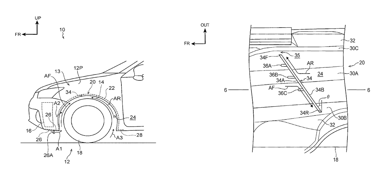
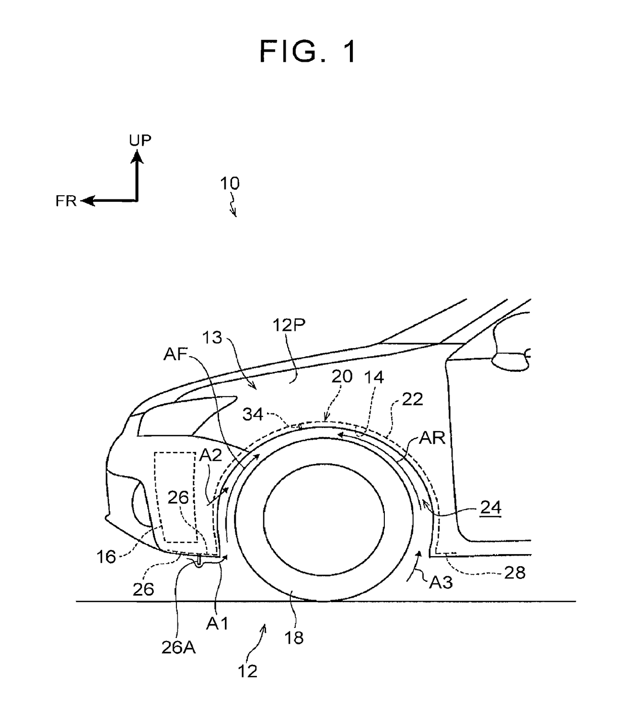
[0033]An embodiment of the present disclosure will be described using drawings. In the drawings, a vehicle-frontward direction is indicated by an arrow FR, an outward direction in the vehicle-width direction is indicated by an arrow OUT, and a vehicle-upward direction is indicated by an arrow UP.

[0034]As shown in FIG. 1, an air flow adjusting structure for a vehicle 12 of the present disclosure is provided on a fender 13 of a vehicle 10. In the present embodiment, the fender 13 on the front left of the vehicle will be illustrated and described, but the same air flow adjusting structure for the vehicle may also be applicable to a fender on the front right of the vehicle.

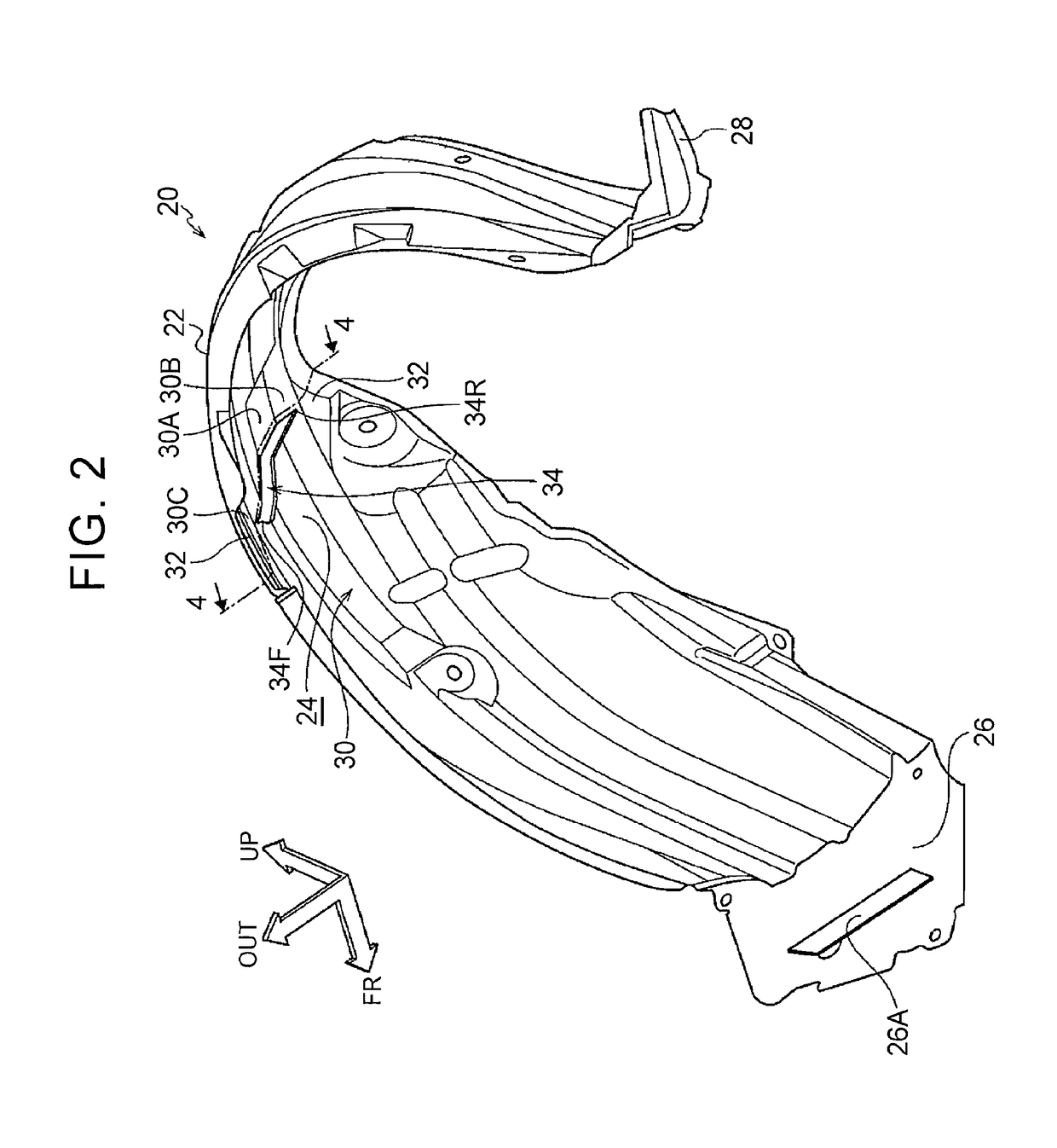
[0035]A front bumper 16 is provided at a front end of the vehicle 10, and the fender 13 is provided at an outer end of a rear part of the front bumper 16 in the vehicle-width direction. A wheel house 14 is formed inward of the fender 13 in the vehicle-width direction, and a fender liner 20 is fixed to an inside of the...


PUM


Abstract

An air flow adjusting structure for a vehicle includes: a fender liner provided above a tire in a vehicle vertical direction, the fender liner including an arch such that an air flow passage is formed between the arch and the tire; and an adjusting rib projecting from the arch in a vehicle-downward direction, the adjusting rib being inclined relative to a vehicle-width direction, and extending in a direction that intersects with a vehicle-longitudinal direction.

Description

INCORPORATION BY REFERENCE[0001]The disclosure of Japanese Patent Application No. 2015-178724 filed on Sep. 10, 2015 including the specification, drawings and abstract is incorporated herein by reference in its entirety.BACKGROUND[0002]1. Field of the Disclosure[0003]The present disclosure relates to an air flow adjusting structure for a vehicle.[0004]2. Description of Related Art[0005]Japanese Patent Application Publication No. 2009-143255 below discloses a fender liner having a flow adjusting groove to guide air. The air introduced from rearward of a wheel house into the wheel house. This straightening groove guides the air from rearward of the wheel house to frontward thereof, and continuously discharges the air from discharge flow passages split at a frontward position to the outside in a vehicle-width direction.SUMMARY[0006]The groove and the plural discharge flow passages are required in the fender liner described in JP 2009-143255 A, which makes the structure complicated.[000...

Claims


Application Information

Patent Timeline
Patent Type & Authority Patents(United States)
IPC IPC(8): B62D25/16B62D25/18B62D37/02
CPCB62D25/161B62D37/02B62D25/18B62D25/16B62D35/00
Inventor UMEMOTO, AKIRA
Owner TOYOTA JIDOSHA KK
Why Eureka
Try Eureka