RFI/EMI shielding enclosure containing wireless charging element for personal electronic devices security
a wireless charging element and wireless charging technology, applied in the field of security devices, can solve the problems of workplace damage to productivity, inability to allow access to mobile phones, and ineffective traditional solutions to prevent malicious or inadvertent use of smartphones, etc., to achieve useful operation, improve security, and reduce the effect of battery loss
- Summary
- Abstract
- Description
- Claims
- Application Information
AI Technical Summary
Benefits of technology
Problems solved by technology
Method used
Image
Examples
first embodiment
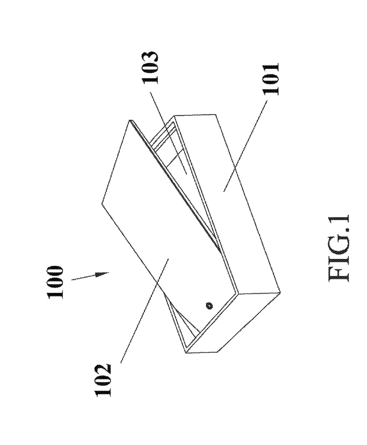
[0041]FIG. 1 illustrates an EMI / RFI shielding enclosure according to the present invention. In this embodiment, the EMI / RFI shielding enclosure 100 is consisted of a lower enclosure 101 and an upper lid 102, and the upper lid 102 is therefore structurally engaging with (and covering) the whole lower enclosure 101. The EMI / RFI shielding enclosure 100 is for example a Faraday cage. The lower enclosure 101 has four sidewalls and a base portion. In one embodiment, the lower enclosure 101 defines a first interlocking portion at two inner lateral sides of the four sidewalls of lower enclosure 101 to interlock a second interlocking portion at two lateral sides of the upper lid 102 by mechanical latches or screws such that the upper lid 102 is capable of pivoting along a parallel axis by pushing vertically to allow for easy access open / close by a user, and the lower enclosure 101 defines a concave space 103 for one electronic device (such as smartphone) disposed on the base portion of the l...
second embodiment
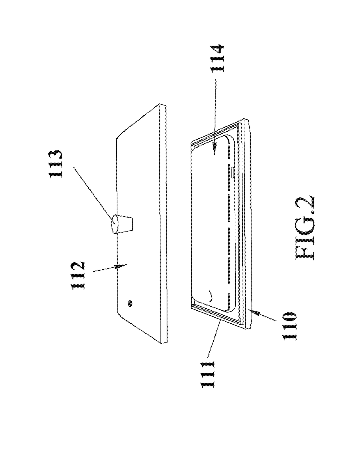
[0047]FIG. 2 illustrates the security enclosure according to the present invention. In this embodiment, the EMI / RFI shielding enclosure is consisted of a lower enclosure 110, an EMI / RFI shielding gasket 111 and an upper lid 112, and the EMI / RFI shielding gasket 111 is configured between the lower enclosure 110 and the upper lid 112 to ensure that the gap does not reduce shielding effectiveness. In this embodiment, the upper lid 112 is configured with a lift pin 113 fixed onto the upper lid 112 for lift-on / lift-off the EMI / RFI shielding enclosure. A concave space (within the lower enclosure 110) is defined between the lower enclosure 110 and the upper lid 112 for receiving one electronic device 114, such as smartphone, which may be disposed on the base portion of the lower enclosure 110. The smartphone 114 can be directly manually disposed on the base portion of the lower enclosure 110, followed by holding the lift pin 113 of the upper lid 112 to close (lift-on) the EMI / RFI shielding...
third embodiment
[0052]FIG. 3 illustrates an EMI / RFI shielding enclosure according to the present invention. In this embodiment, the EMI / RFI shielding enclosure 120 is consisted of a lower enclosure 121 and an upper lid 122, and the upper lid 122 is structurally engaging with (and covering) the whole lower enclosure 121. The EMI / RFI shielding enclosure 120 is a Faraday cage. The lower enclosure 121 has four sidewalls and a base portion. The EMI / RFI shielding enclosure 120 is a multiple device holder, and therefore the lower enclosure 121 defines a receiving (accommodating) space 123 for multiple electronic devices (such as multiple smartphones) 124 disposed on the base portion of the lower enclosure 121. The shape of the enclosure 120 shown in FIG. 3 takes the form of a rectangular; however the invention is not limited in this respect. Multiple smartphones 124 can be directly manually disposed on the base portion of the lower enclosure 121, followed by pushing rear end of the upper lid 122 for slidi...
PUM
 Abstract
Description
Claims
Application Information
 - R&D
- Intellectual Property
- Life Sciences
- Materials
- Tech Scout
- Unparalleled Data Quality
- Higher Quality Content
- 60% Fewer Hallucinations
Browse by: Latest US Patents, China's latest patents, Technical Efficacy Thesaurus, Application Domain, Technology Topic, Popular Technical Reports.
© 2025 PatSnap. All rights reserved.Legal|Privacy policy|Modern Slavery Act Transparency Statement|Sitemap|About US| Contact US: help@patsnap.com


