Method and system for opportunistic delivery of less-than-best-effort application data over communication networks

a communication network and application data technology, applied in the field of communication, can solve problems such as the difficulty of the ran itself to inspect the data packets flowing through, and achieve the effect of reducing the overload of network resources

Active Publication Date: 2018-07-24
LUCENT TECH INC
View PDF15 Cites 0 Cited by
  • Summary
  • Abstract
  • Description
  • Claims
  • Application Information

AI Technical Summary

Benefits of technology

[0011]An embodiment of the present invention relates to a method and system for packet delivery from an application server to a mobile client in a wireless network, e.g. for reducing network resource overload caused by chatty applications. The wireless network includes one or more base stations and one or more upstream network entities, e.g., a radio network controller (“RNC”), connected to the base station(s). The upstream network entities include necessary components (e.g., a packet data serving node (“PDSN”)) to enable communication between an application server connected to the Internet and the end user mobile clients. The base station wirelessly communicates with a set of distributed end user mobile clients, e.g., mobile phones. The RNC (or other upstream network entity) acts as an interface between the base station and the upstream portion of the network. Thus, during communication, as the RNC receives data flows from an application server designated for transmission to the end user mobile clients, the data flows are transmitted to the base station. (A “flow” is a uniquely defined stream of data packets between a source address / port and a destination address / port, wherein the packets are generated according to the same protocol.) The data flows over the RAN typically include tunneled or encrypted data packets, and therefore, it is very difficult for the RAN itself to inspect the data packets flowing through. The network additionally includes a wireless information node (“WIN”) network having at least one wireless information node and at least one wireless information database. The WIN network is connected to the RAN network such that the WIN network is capable of detecting an element of the RAN network servicing the mobile client, e.g. the RNC or base station with which the mobile client is wirelessly communicating. Additionally, the WIN network is adapted for connection to the application server, e.g. information may be transmitted between the WIN network and the application server. Since the WIN network is connected to both the RAN network and the application server, the WIN network provides linkage between the IP data flows and the RAN elements or nodes that are delivering the flows to the mobile client, thereby eliminating the need for the RAN to inspect the data packets flowing through the RAN network.
[0012]In operation, an application server registers with the WIN network to be notified when the mobile client with which communication is desired transitions to or from a connected state, e.g. from an idle state to a connected state. The WIN network detects the element(s) in the RAN network serving the mobile client and subscribes with the element(s) to be notified when the connection state changes. The element(s) serving the mobile client detects the connection state of the mobile client and notifies the WIN network of a change in the connection state of the mobile client, e.g. from idle to connected. The WIN network in turn notifies the application server of the change in the connection state of the mobile client, whereby the application server delivers packets to the mobile client upon notification of a connected state at the application server. Since the WIN network is connected to both the RAN network and the application server, the WIN network eliminates the need for the RAN to inspect the data packets flowing through the RAN network because the WIN network provides a linkage between the IP data flows and the RAN elements or nodes that are delivering the flows to the mobile client.
[0013]In another embodiment, the RAN network automatically delays paging to initiate delivery of network initiated non-latency sensitive data, e.g. the data from an application server having Quality of Service (“QoS”) requirements that allow the data to be delivered in the background. An application server registered with the WIN network may bypass the automatic delay by sending a page request to the WIN network, the WIN network triggering paging upon receipt of the page request.

Problems solved by technology

The data flows over the RAN typically include tunneled or encrypted data packets, and therefore, it is very difficult for the RAN itself to inspect the data packets flowing through.

Method used


Image

  • Method and system for opportunistic delivery of less-than-best-effort application data over communication networks
  • Method and system for opportunistic delivery of less-than-best-effort application data over communication networks
  • Method and system for opportunistic delivery of less-than-best-effort application data over communication networks

Examples


Embodiment Construction

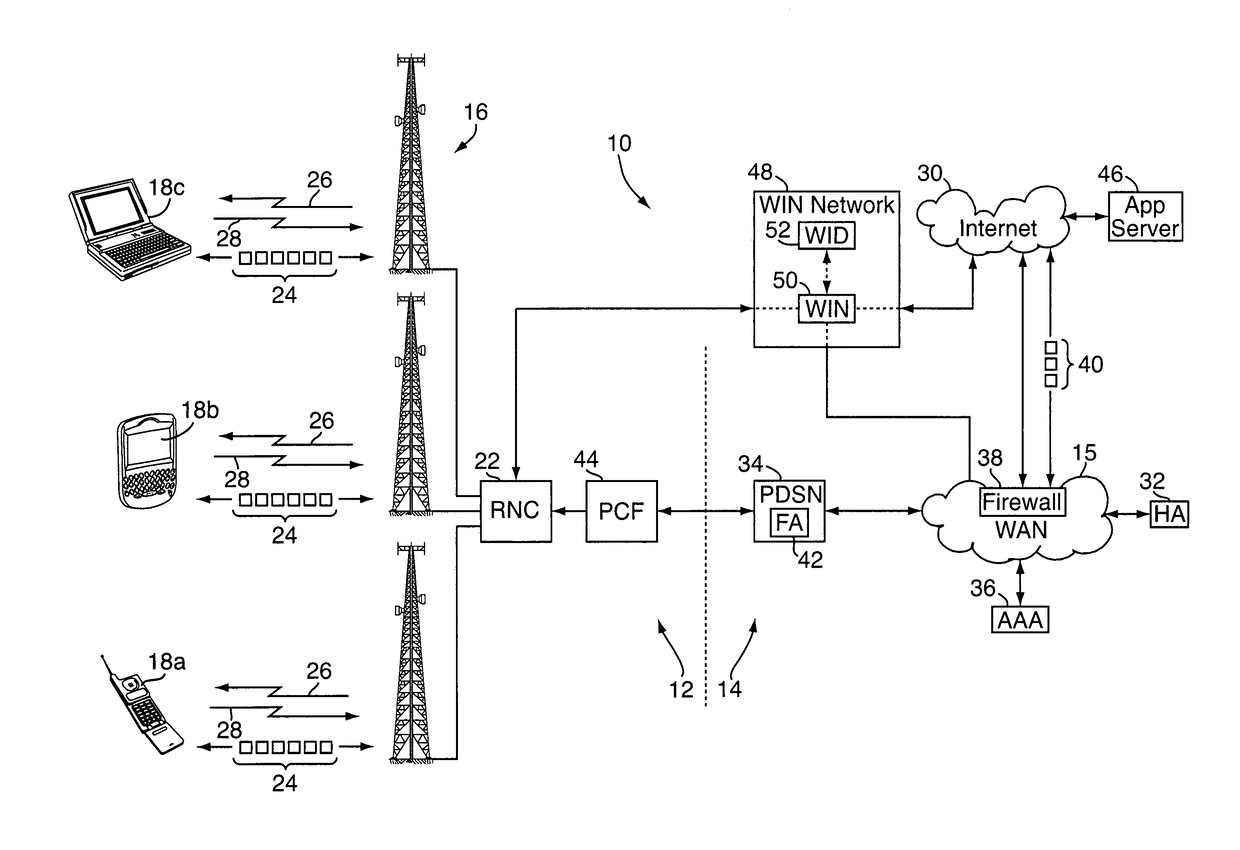
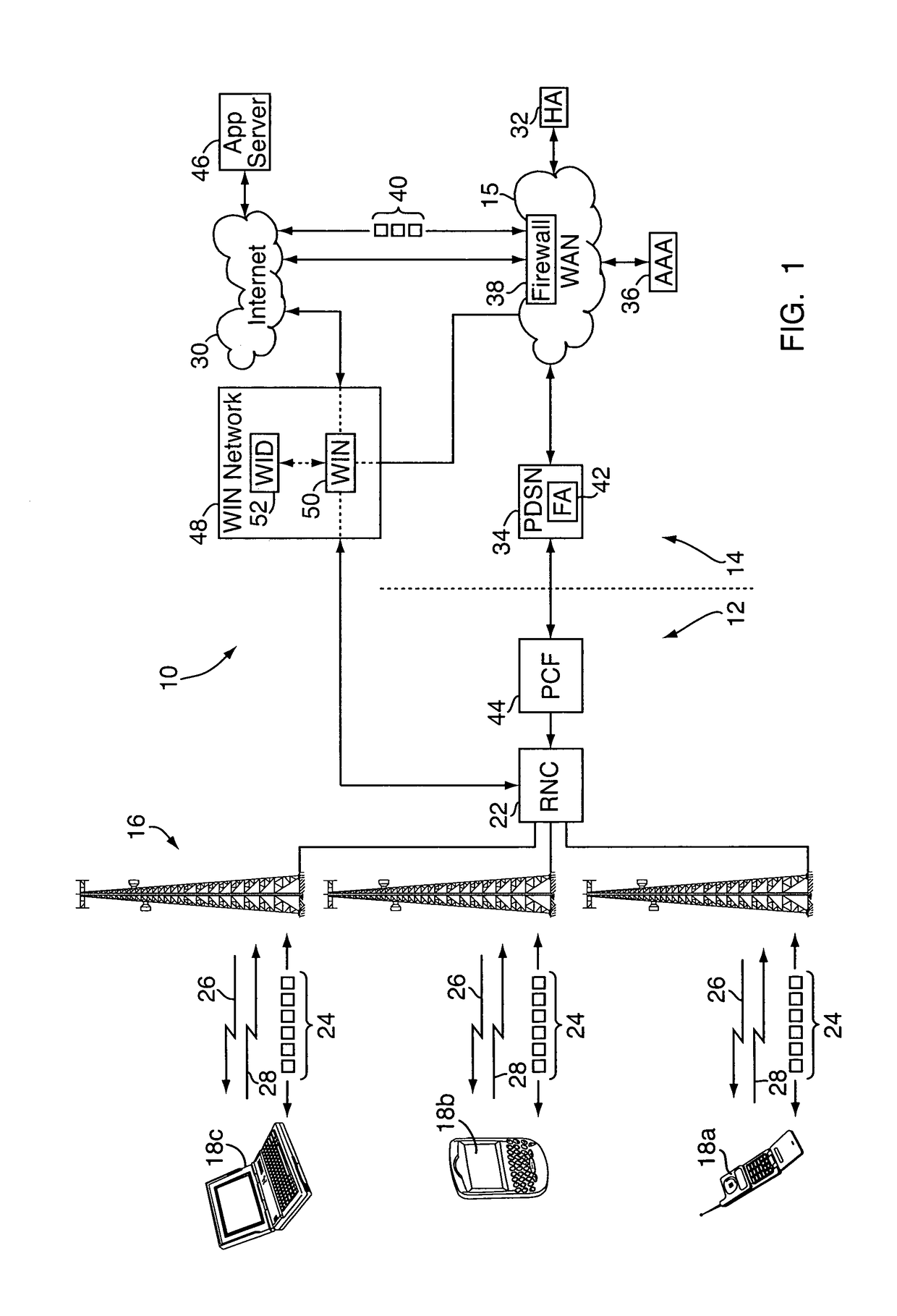
[0024]With reference to FIG. 1, an embodiment of a method and apparatus for opportunistic delivery of less-than-best-effort application data are implemented on or as part of a wireless communication network 10, e.g., a CDMA-based 1×-EVDO network or other wireless network. The wireless network 10 may include a radio access network (“RAN”) portion 12 and a core IP (Internet Protocol) portion 14, which contains a carrier wide area network (“WAN”) 15. Although for simplicity, the WAN 15 is shown connected to a single RAN portion 12, it should be understood that multiple RAN portions 12 would be implemented to provide large wireless network coverage area. The RAN portion 12 includes one or more fixed base stations 16, each with various transceivers and antennae for wireless radio communications with a number of distributed wireless mobile clients 18a-18c, e.g., mobile phones, “3-G” (third generation) wireless devices, wireless computers, and the like. The base stations 16 are in turn con...


PUM


Abstract

In a method and system for opportunistic delivery of less-than-best-effort application data, a WIN network identified the elements of the wireless network servicing a specified mobile client. One or more elements of the wireless network servicing the specified mobile client monitor the connection state of a mobile client and notify the WIN network of connection state changes so that a chatty application running on an external application server may be notified by the WIN network to deliver packet data when the specified mobile client is connected to the network for some other purpose or when unused network resources are available. In this way, network resource overload caused by chatty applications is reduced.

Description

FIELD OF THE INVENTION[0001]The present invention relates to communications and, more particularly, to methods and systems for controlling data flow in wireless communication networks.BACKGROUND OF THE INVENTION[0002]Wireless radio frequency communication systems enable people to communicate with one another over long distances without having to access landline-connected devices such as conventional telephones. While early systems were primarily configured for voice communications, technological improvements have enabled the development of “3-G” (third generation) and similar wireless networks for both voice and high-speed packet data transfer. For example, CDMA-based, “1×-EVDO” (Evolution Data Optimized, or Evolution Data Only) wireless communication networks, now implemented in many parts of the U.S. and elsewhere, use the CDMA2000® 3-G mobile telecommunications protocol / specification for the high-speed wireless transmission of both voice and non-voice data. 1×-EVDO is an implemen...

Claims


Application Information

Patent Timeline
Patent Type & Authority Patents(United States)
IPC IPC(8): H04L29/08
CPCH04L67/24H04L67/54
Inventor BRYSON, SIDNEY LLEWELLYNROSSETTI, DAVID ALBERTRUBIN, HARVEYVARNEY, DOUGLAS WILLIAM
Owner LUCENT TECH INC
Why Eureka
Try Eureka