System and method for thermal response testing

a technology of thermal response and system, applied in the field of thermal response testing, can solve the problems of unsafe solutions and inefficiency of instruments

Active Publication Date: 2018-08-14
ENERGIE STAT
View PDF4 Cites 3 Cited by
  • Summary
  • Abstract
  • Description
  • Claims
  • Application Information

AI Technical Summary

Problems solved by technology

However, such instrumentation is typically bulky, thereby causing delays due to mobilizing and demobilizing thereof.
In addition, the instrumentation can present an unsafe solution due to exposed cables or pipes.
Moreover, on-site operators are typically required to operate the tests, proving inefficient in some cases.

Method used


Image

  • System and method for thermal response testing
  • System and method for thermal response testing
  • System and method for thermal response testing

Examples


Embodiment Construction

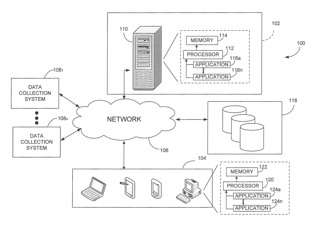
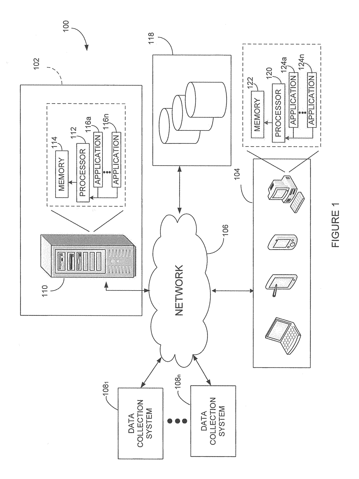
[0030]Referring now to FIG. 1, a system 100 for performing a thermal response test will now be described. The system 100 comprises a testing system 102, which may communicate with a plurality of devices 104 via a network 106, such as the Internet, a cellular network, or others known to those skilled in the art. The devices 104 may further enable users, such as technicians and operators, to access the testing system 102 and may comprise any device, such as a computer, e.g. a laptop or a desktop computer, a personal digital assistant (PDA), a smartphone, or the like, adapted to communicate over the network 106. Each device 104 may access the testing system 102 over the network 106 through routers (not shown) or other suitable devices. The testing system 102 may also be in communication with one or more data collection systems 1081, . . . , 108n over the network 106 in order to operate the desired thermal response tests, e.g. thermal conductivity tests, as will be discussed further bel...


PUM

PropertyMeasurementUnit
weightaaaaaaaaaa
widthaaaaaaaaaa
lengthaaaaaaaaaa

Abstract

A system and method for performing at least one thermal response test for a medium. At least one request signal indicative of at least one request to perform the thermal response test is received. On the basis of the at least one request, at least one control signal is generated for causing at least one parameter of a fluid circulating through the medium to be acquired. The at least one measurement is indicative of a thermal property of the medium. The at least one control signal is then output to a hydraulic system.

Description

CROSS-REFERENCE TO RELATED APPLICATIONS[0001]This patent application claims priority of U.S. provisional Application Ser. No. 61 / 805,354, filed on Mar. 26, 2013, the contents of which are hereby incorporated by reference.TECHNICAL FIELD[0002]The present invention relates to the field of thermal response testing.BACKGROUND OF THE ART[0003]Thermal response tests, such as thermal conductivity tests, are performed to assist in the design and installation of sustainable ground source heating or cooling solutions. For this purpose, a fluid is passed through a test borehole loop and testing instrumentation is used to record data throughout the duration of the test. However, such instrumentation is typically bulky, thereby causing delays due to mobilizing and demobilizing thereof. In addition, the instrumentation can present an unsafe solution due to exposed cables or pipes. Moreover, on-site operators are typically required to operate the tests, proving inefficient in some cases.[0004]Ther...

Claims


Application Information

Patent Timeline
Patent Type & Authority Patents(United States)
IPC IPC(8): G01N25/18
CPCF24T10/15F24T2201/00Y02E10/125Y02E10/10
Inventor KWEMO, PATRICE
Owner ENERGIE STAT
Why Eureka
Try Eureka