Asset life optimization and monitoring system

a monitoring system and asset technology, applied in the field of asset life optimization and monitoring systems, can solve the problems of inability to determine the thickness of the furnace wall on hot furnaces, the inability to monitor the status of the asset, and the deformation of the inner walls of the refractory chamber of the furnace during operation, so as to optimize the maintenance schedule of costly and potentially risky assets. , the effect of increasing the effective evaluation, monitoring, diagnosing or tracking

Active Publication Date: 2018-08-21
PANERATECH
View PDF15 Cites 2 Cited by
  • Summary
  • Abstract
  • Description
  • Claims
  • Application Information

AI Technical Summary

Benefits of technology

[0012]An improved system to evaluate and monitor the status of a material forming part of an asset, such as a refractory furnace, is disclosed herein. One or more aspects of exemplary embodiments provide advantages while avoiding disadvantages of the prior art. The system is operative to identify flaws and measure the erosion profile and thickness of different materials, including (by way of non-limiting example) refractory materials of an industrial furnace, using radiofrequency signals. The system is designed to integrate software with a plurality of sensors and additional hardware to collect data during an inspection of the furnace, even in regions of difficult access. Furthermore, the system comprises a software management subsystem configured to implement signal processing techniques to process the data collected and generate reports to visualize the status, estimate the remaining operational life, and determine and report the level of penetration of molten material into the surrounding layers of the furnace. Moreover, the system's software enables a user to monitor the status of the furnace both locally and remotely.
[0014]The computer-based processor determines the delay in time between the reference signal and other reflected signals, which may include undesired clutter. Where the magnitude of the clutter is below the magnitude of the signals reflected from remote discontinuities of the material, the computer-based processor identifies a peak level of magnitude associated with these discontinuities and determines the distance from such discontinuities to the surface of the material contiguous to the antenna. One or more evaluations over an area of the material provides the residual thickness of the material and the location of flaws inside the material at each evaluation to create an erosion profile of the remote surface of the material.
[0015]In addition, the use of one or more antennas having an alternate configuration and the corresponding data processing allows the generation of cross-sectional images of the inside of the material under evaluation. This becomes particularly useful when evaluating a multilayered structure, such as the layers of refractory material surrounding the molten material in an industrial furnace. As a result, the system is capable of creating a tomographic view within the different layers of material to identify the location of remote discontinuities. More importantly, the system allows for the visualization of the presence of extraneous material within the material under evaluation, such that the penetration of molten material into the insulating material can be detected early.
[0016]Therefore, by determining the rate of penetration of molten material into the surrounding material, it is possible to estimate the remaining operational life of the furnace, effectively extending the life of the furnace. This allows more effective and accurate scheduling to optimize the costly processes of furnace repairs, decommissioning, or replacement along with a significant reduction of the level of risk of an operational break or leakage of molten material.
[0018]By integrating a number of sensors, additional hardware, and a software management subsystem, and thereby significantly increasing the effective evaluation, monitoring, diagnosing, or tracking of one or more conditions related to the operational health of a furnace, as compared to standard techniques, the system is able to identify and determine the location of flaws and optimize the maintenance scheduling of costly and potentially risky assets.

Problems solved by technology

However, the inner walls of the refractory chamber of the furnace will degrade during operation.
The effects of this degradation include inner surface erosion, stress cracks, and refractory material diffusion into the molten material.
However, these efforts have faced certain challenges and limitations.
In particular, attempts made to determine furnace wall thickness on hot furnaces have been generally unsuccessful because of the large signal losses involved in evaluating the inner surface of refractory materials, especially at relatively high frequency bands.
Likewise, at relatively low frequency bands signals still experience losses and are limited in terms of the bandwidth and resolution required by existing systems.
Moreover, in placing system components close to the surface of the refractory material to be evaluated, spurious signal reflections make it difficult to isolate the reflected signal of interest, thus further complicating the evaluation of the status of either the inner surface or the interior of such materials.
A major challenge is that furnace walls become more electrically conductive as temperature increases.
Therefore, signals going through a hot furnace wall experience significant losses making the detection of these signals very challenging.
In addition, these attempts have focused on standalone systems lacking integration as a single solution, further requiring software for maximizing the extraction of information from the measured data, and facing challenges to access areas of difficult access in an industrial environment.
As a result, these systems are not able to monitor and evaluate a large asset, such as an industrial furnace, for optimizing its operational life, without the support of tracking and software tools.
Currently, there is no well-established integrated system of deterministically and effectively measuring the rate of penetration of molten material into the surrounding refractory material to optimize both the operational life and the maintenance plan of the furnace.
As a result, manufacturers experience either an unexpected leakage of molten material through the furnace wall or conservatively shut down the furnace for re-build to reduce the likelihood of any potential leakage, based on the manufacturer's experience of the expected lifetime of the furnace.
Each of these factors is subject to uncertainties that make it difficult to create accurate estimates of the expected lifetime of a furnace.
Moreover, the flow of molten material, such as molten glass, at high temperatures erodes and degrades the inner surface of the refractory material and creates a high risk for molten glass leakage through the refractory wall.
A major leak of molten glass through the gaps and cracks in the furnace walls may require at least 30 days of production disruption before the furnace can be restored to operating mode because it needs to be cooled down, repaired, and fired up again.
Furthermore, a leak of molten glass may cause significant damage to the equipment around the furnace and, most importantly, put at risk the health and life of workers.
This leads to significant costs for manufacturers in terms of their initial investment and the reduced production capacity over the operational life of the furnace.
Another important issue is that the material used to build the refractory chamber of the furnace may have internal flaws not visible by surface inspection.
This could translate into a shorter life of the furnace and pose serious risks during furnace operation.

Method used


Image

  • Asset life optimization and monitoring system
  • Asset life optimization and monitoring system
  • Asset life optimization and monitoring system

Examples


Embodiment Construction

[0026]The following description is of particular embodiments of the invention, set out to enable one to practice an implementation of the invention, and is not intended to limit the preferred embodiment, but to serve as a particular example thereof. Those skilled in the art should appreciate that they may readily use the conception and specific embodiments disclosed as a basis for modifying or designing other methods and systems for carrying out the same purposes of the present invention. Those skilled in the art should also realize that such equivalent assemblies do not depart from the spirit and scope of the invention in its broadest form.

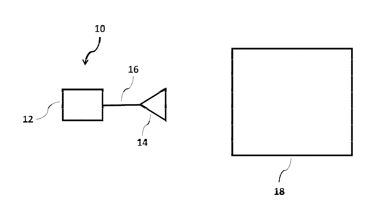
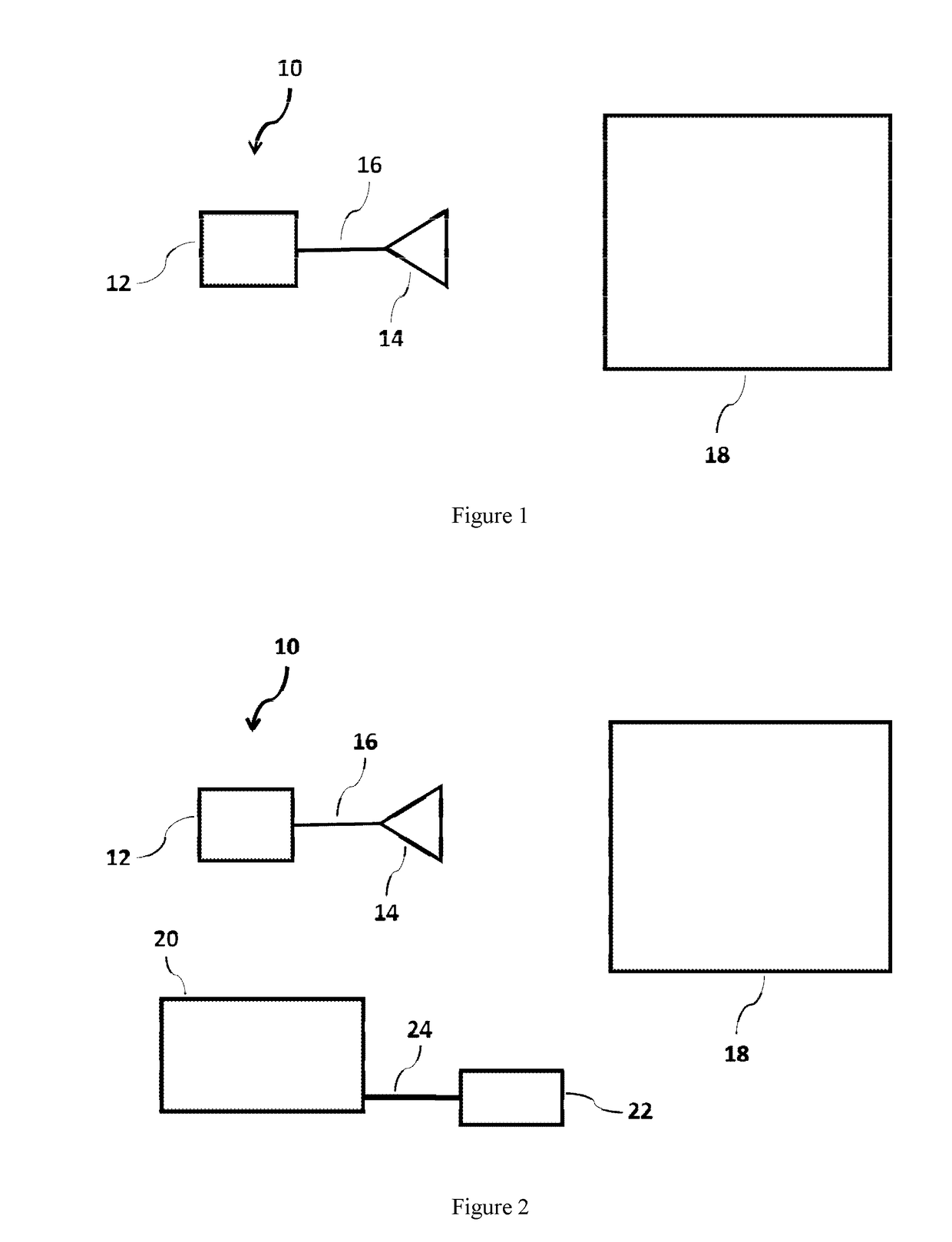
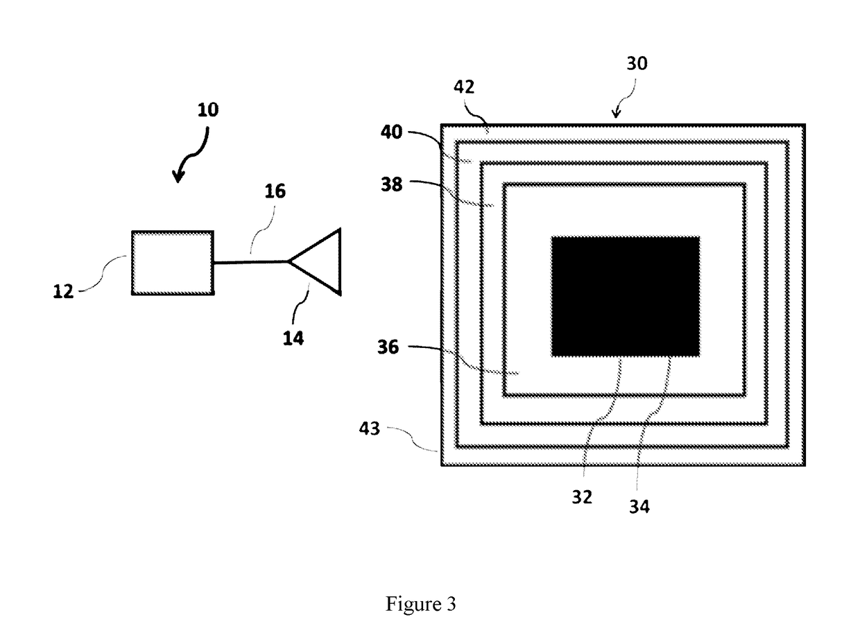
[0027]In accordance with certain aspects of a configuration of the invention, a schematic top view of the components of a monitoring system 10, used for a typical application of evaluating and monitoring or inspecting a unit under test (UUT) 18, is shown in FIG. 1. Monitoring system 10 comprises a control unit 12, a sensor head 14, and a set of c...


PUM

PropertyMeasurementUnit
frequencyaaaaaaaaaa
thicknessaaaaaaaaaa
temperaturesaaaaaaaaaa

Abstract

Disclosed is a system to evaluate and monitor the status of a material forming part of an asset, such as a refractory furnace. The system is operative to identify flaws and measure the erosion profile and thickness of different materials, including refractory materials of an industrial furnace, using radiofrequency signals. The system is designed to integrate software with a plurality of sensors and additional hardware to collect data during an inspection of the furnace, even in regions of difficult access. Furthermore, the system comprises a software management subsystem configured to implement signal processing techniques to process the data collected and generate reports to visualize the status, estimate the remaining operational life, and determine the level of penetration of molten material into the surrounding layers of the furnace. Moreover, the system's software enables a user to monitor the status of the furnace both locally and remotely.

Description

CROSS REFERENCE TO RELATED APPLICATION[0001]This application is based upon and claims priority from U.S. Provisional Patent Application Ser. No. 62 / 247,869 entitled “ASSET LIFE OPTIMIZATION AND MONITORING SYSTEM” filed with the U.S. Patent and Trademark Office on Oct. 29, 2015, by the inventors herein, the specification of which is incorporated herein by reference.FIELD OF THE INVENTION[0002]The present invention relates to systems for evaluating the status of a material. More particularly, the present invention relates to systems for monitoring and determining the condition of refractory material using radiofrequency signals.BACKGROUND OF THE INVENTION[0003]A number of evaluation and monitoring systems have been disclosed within various industries for measuring the properties during and after formation of certain materials, using radiofrequency signals. The surface characteristics, internal homogeneity, thickness, and rate of erosion of a material are some of the important attribut...

Claims


Application Information

Patent Timeline
Patent Type & Authority Patents(United States)
IPC IPC(8): G01N22/02G01B15/02F27D21/00
CPCF27D21/0021G01N22/02G01B15/025
Inventor BAYRAM, YAKUPRUEGE, ALEXANDERKNOWLES, JUSTIN
Owner PANERATECH
Why Eureka
Try Eureka