
Roller bearing and hydrostatic axial piston machine of swashplate design with a roller bearing

Active Publication Date: 2018-08-28
ROBERT BOSCH GMBH
View PDF9 Cites 1 Cited by
  • Summary
  • Abstract
  • Description
  • Claims
  • Application Information

AI Technical Summary

Benefits of technology

The patent text describes a new design for roller bearings and axial piston machines. The new design allows for tolerating tilting or oblique positioning of one of the raceways without being restricted to barrel-shaped or spherical rolling elements with a reduced contact width. The roller elements can be spherical or barrel-shaped, increasing the tolerance of tilting or ob devient further. The design is simple to manufacture and can be extended over the entire length or circumference of the bearing shell. The patent aims to provide a more robust and flexible solution for applications where tilting or ob container position is necessary.

Problems solved by technology

Between the circular-arc-shaped tracks of each bearing, this results in a disadvantageous change in the positions of the tracks with respect to one another since the swivel-cradle track tilts in relation to the housing track and comes into an oblique position.
A disadvantage of such axial piston machines is that the barrel-shaped rolling elements always only have a reduced contact width, i.e. a reduced linear contact.
The bearing properties of the rolling elements are therefore disadvantageously affected.

Method used


Image

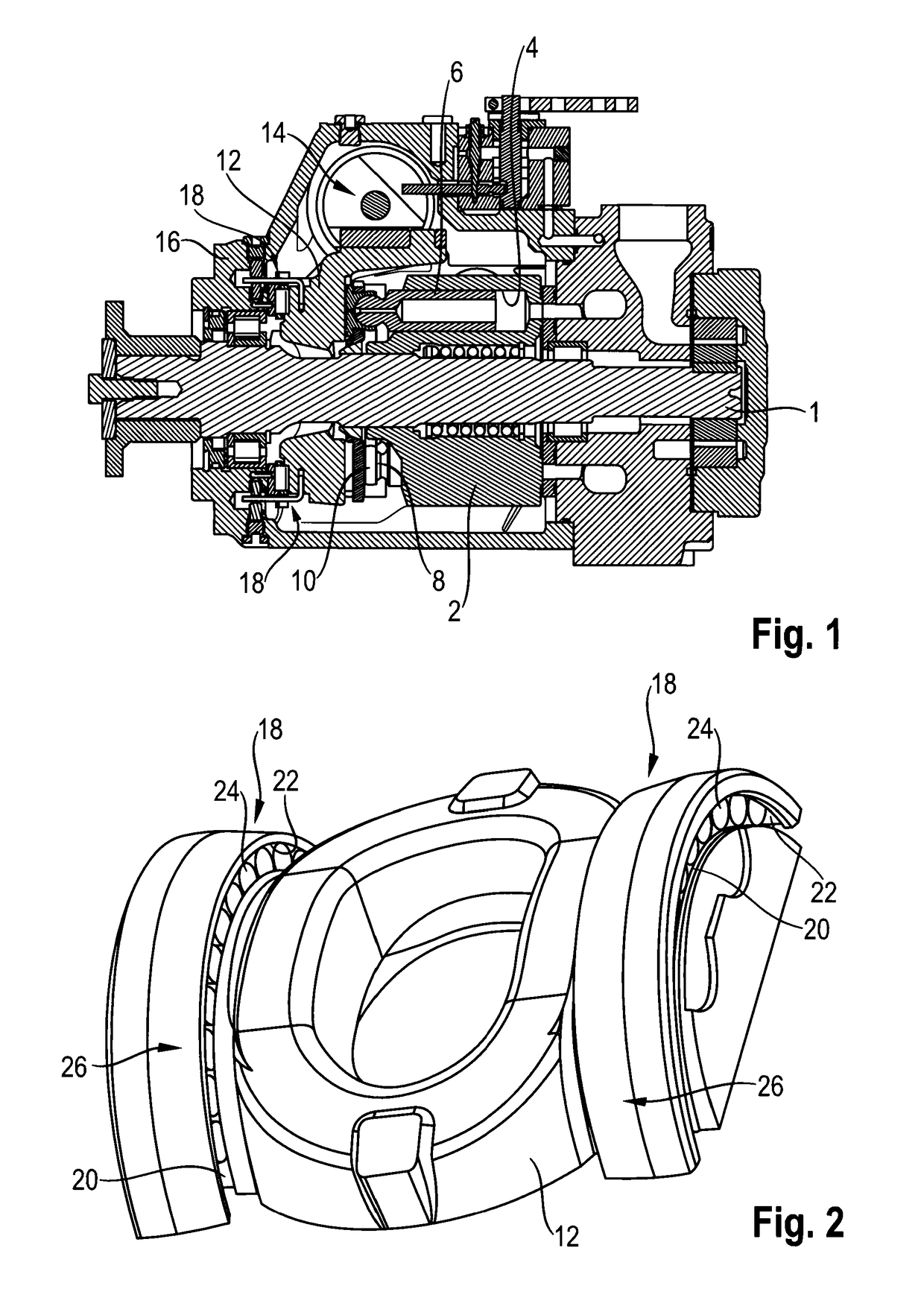
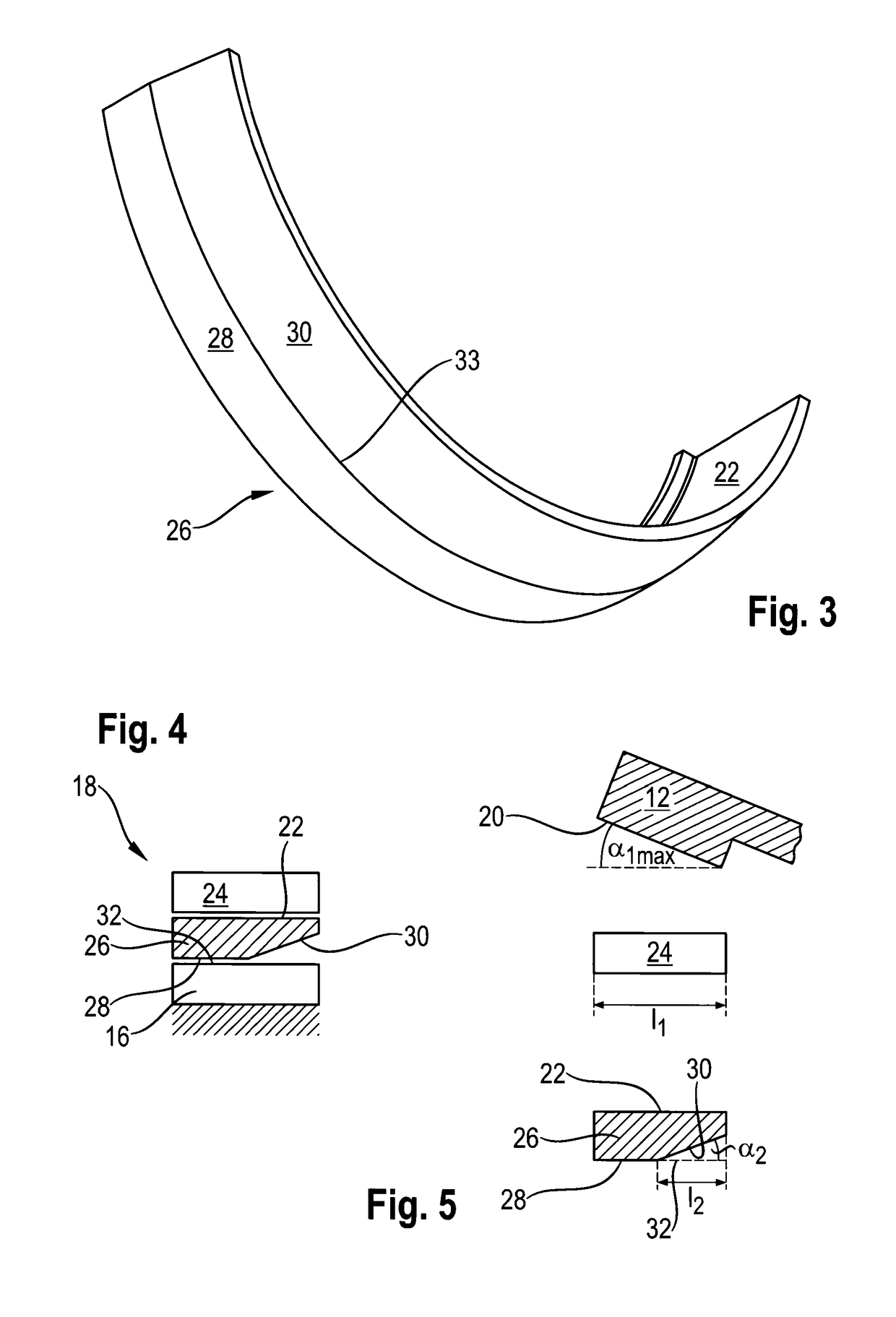
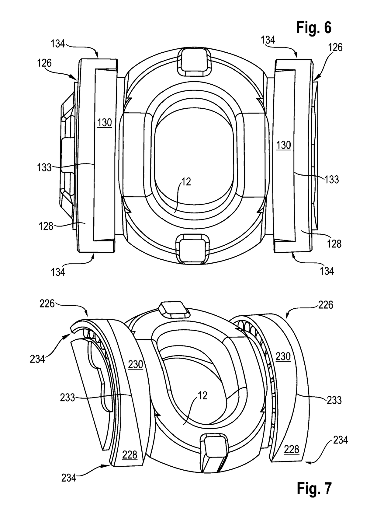
  • Roller bearing and hydrostatic axial piston machine of swashplate design with a roller bearing
  • Roller bearing and hydrostatic axial piston machine of swashplate design with a roller bearing
  • Roller bearing and hydrostatic axial piston machine of swashplate design with a roller bearing

Examples


second embodiment

[0065]FIG. 11 shows, in a cross section, a detail of a bearing shell 626 according to the roller bearing according to the disclosure in an intermediate state of the manufacturing of said bearing shell. An outer circumferential surface 631 has, by means of turning, obtained a diameter which is initially still larger than that which the contact region 628 of the final bearing shell 626 will have.

first embodiment

[0066]The reduced region 630 is produced in a width 1 by turning and—in a departure from the first embodiment according to the preceding figures—has a circular-cylindrical shape.

[0067]A step which has a radial flank 637, at least in the intermediate state according to FIG. 11, is formed between the reduced region 630 and the outer circumferential surface 631. A transition 638 between the reduced region 630 and the flank 637 is rounded with a radius R. The latter can be, for example, 0.4 mm

[0068]In a manufacturing step following the turning, the bearing shell 626 is heat-treated and therefore hardened.

[0069]FIG. 12 shows, in a cross section, a detail of the finished bearing shell 626 from FIG. 11 after the heat treatment and after the grinding of the outer circumferential surface 631 to the size of the contact portion 628. The radial flank 637 has also been substantially removed. This forms an edge 633 which is arranged between the rounded transition 638 and the contact portion 628. ...


PUM


Abstract

A rolling bearing includes rollers clamped between an inner raceway and an outer bearing shell. The outer bearing shell bears with its outer circumferential surface against an outer component which can be a housing of an axial piston machine. The inner raceway is either formed directly on an inner component, or it is formed on an inner bearing shell, which bears against the inner component. In order to permit tilting of the inner component, wherein the rollers remain in predetermined contact with the two raceways, at least one beveled contact region or a region reduced in another way is provided on the outer circumferential surface of the outer bearing shell.

Description

[0001]This application claims priority under 35 U.S.C. § 119 to patent application number DE 10 2015 209 798.6, filed on May 28, 2015 in Germany, and patent application number DE 10 2016 208 286.8, filed on May 13, 2016 in Germany, the disclosures of which are incorporated herein by reference in their entireties.BACKGROUND[0002]The disclosure relates to a roller bearing and to an axial piston machine of swashplate design with such a roller bearing.[0003]In the case of axial piston machines, the working volume of which is adjustable, it is known to design a swashplate as a swivel cradle which can be swiveled towards a housing via an adjustment device. By adjusting the swivel angle of the swivel cradle in relation to a cylinder drum revolving about an axis, the stroke of the pistons coupled to the swashplate is adjusted during their revolution about an axis of the axial piston machines.[0004]Since, during the adjustment of the swivel angle, the swivel cradle is moved relative to the h...

Claims


Application Information

Patent Timeline
IPC IPC(8): F16C33/58F16C19/50F16C27/04F04B1/12F01B3/00F04B1/20
CPCF16C33/586F04B1/128F04B1/2014F04B1/2078F16C19/502F16C27/04F04B1/2085F16C2360/00F01B3/0073
Inventor ROMER, ACHIMASSFALG, CHRISTOPH
Owner ROBERT BOSCH GMBH
Learn More