Tank device, a vehicle, and a method for evaluating an output of a pressure sensor

a pressure sensor and output technology, applied in the direction of fluid pressure measurement, electric devices, liquid/fluent solid measurement, etc., can solve the problems of reliability failure evaluation and normality/abnormality evaluation of the output of the sensor, and deviation from each otter, so as to prevent deterioration of reliability

Active Publication Date: 2018-08-28
TOYOTA JIDOSHA KK
View PDF18 Cites 0 Cited by
  • Summary
  • Abstract
  • Description
  • Claims
  • Application Information

AI Technical Summary

Benefits of technology

[0009]The tank device of the above aspect detects the gas pressure of the fuel gas tank by the first pressure sensor when gas is filled in the fuel gas tank, and when fuel gas is first supplied from the fuel gas tank to the gas consuming device after the gas filling, detects the gas pressure of the fuel gas supplied from the fuel gas tank to the gas consuming device by the second pressure sensor in the gas supply pipeline extending from the fuel gas tank to the gas consuming device. Since gas is not consumed during the gas filling and the initial gas supply thereafter, the gas pressure in the fuel gas tank remains nearly the same. Also, the first and second pressure sensors are capable of detecting the filled gas pressure with nearly the same detection range, and the deviations of detection characteristics occur approximately to the same extent in both sensors. Therefore, in the output evaluation based on the gas pressure differential between the gas pressure detected by the first pressure sensor when the fuel tank is filled with gas and the gas pressure detected by the second pressure sensor when fuel gas is first supplied after the gas filling, the deviations of detection characteristics may possibly cancel each other. Then, the pressure of the fuel gas supplied from the fuel gas tank to the gas consuming device turns out equal to the gas pressure of the fuel gas tank during the gas supply. As a result, according to the tank device of the above aspect, deterioration of reliability is prevented in the output evaluation using the sensor output of the second pressure sensor that detects the pressure in fuel gas tank daring the gas supply. Meanwhile, since the tank device of the above aspect can also detect output abnormality in either of the first and second pressure sensors if the gas pressure differential between the gas pressure detected by the first pressure sensor when fuel gas tank is filled with gas and the gas pressure detected by the second pressure sensor when fuel gas is first supplied after the gas filling, deterioration of reliability in the evaluation of output abnormalities is prevented.
[0016]According to the method for evaluating an output of the pressure sensor of the above aspect, deterioration of reliability is prevented in the output evaluation using the sensor output of the second pressure sensor that detects the gas pressure of the fuel gas tank during the gas supply. Also, according to the output evaluation method of this aspect, there is a judgment that there is an output abnormality in either of the first and second pressure sensors if the pressure differential between the gas pressure detected by the first pressure sensor during the gas supply to the fuel gas tank and the gas pressure detected by the second pressure sensor during the initial gas supply after the gas filling is beyond the given threshold value, and deterioration of reliability regarding this judgment on the output abnormality can also be prevented.

Problems solved by technology

Therefore, detection characteristics of the pressure sensor that detects the secondary-side gas supply pressure and those of the pressure sensor that detects the gas pressure of the gas tank often deviate from each otter as time goes by.
Also, if the detected value of the pressure sensor on the gas tank side is deviated, reliability of failure evaluation and normality / abnormality evaluation of the sensor output is at risk.

Method used


Image

  • Tank device, a vehicle, and a method for evaluating an output of a pressure sensor
  • Tank device, a vehicle, and a method for evaluating an output of a pressure sensor
  • Tank device, a vehicle, and a method for evaluating an output of a pressure sensor

Examples


first embodiment

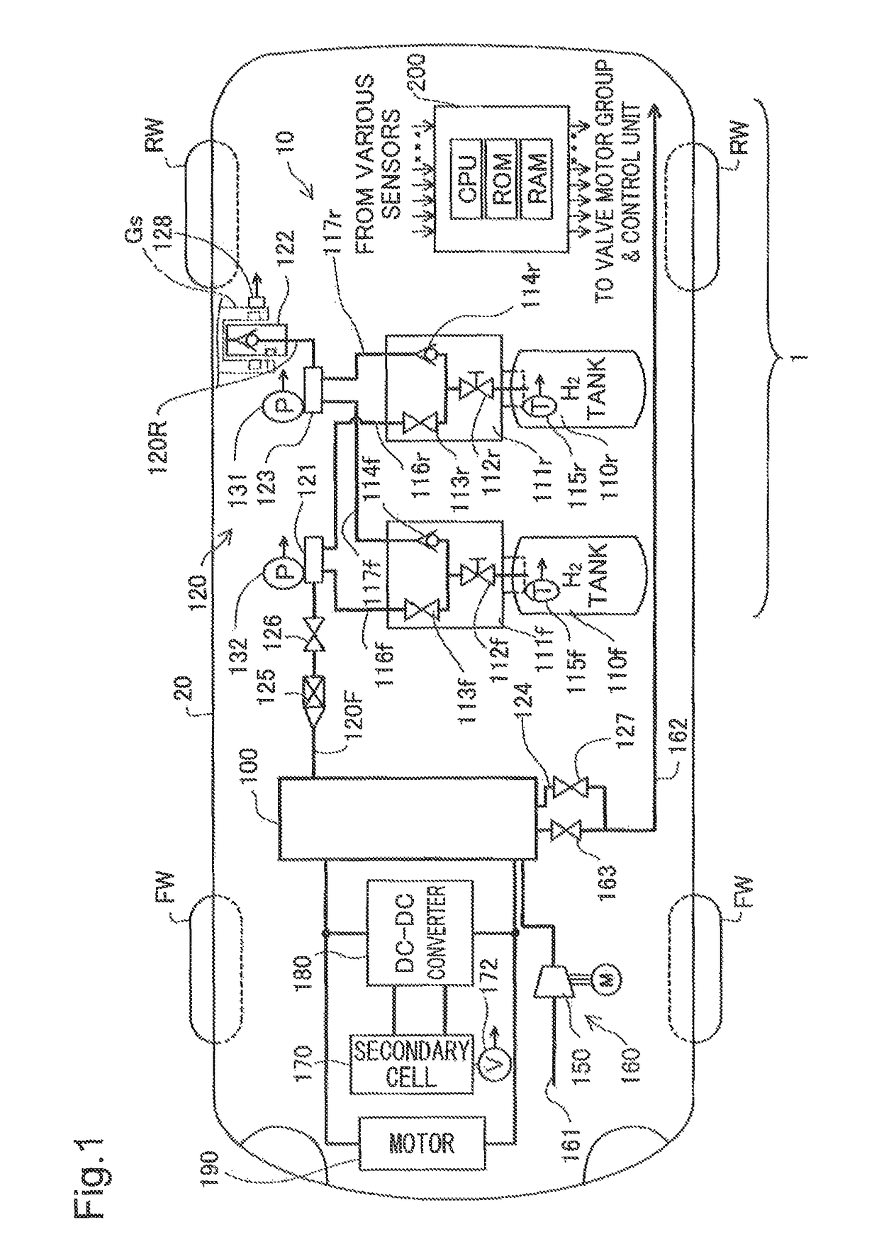
[0024]Embodiments of the present invention are described below in reference to the drawings. FIG. 1 is an illustrative diagram schematically showing a fuel cell system 10 equipped with a tank device 1 as the present invention.

[0025]As shown in the drawing, this tank device 1 is built in the fuel cell system 10 as part thereof. The fuel cell system 10 is mounted on a fuel cell vehicle 20 and comprises a fuel cell 100, a hydrogen gas supply system 120 including two gas tanks, an air supply system 160 including a motorized compressor 150, a cooling system, not shown, a secondary cell 170, a DC-DC converter 130, and a control unit 200. The fuel cell 100 is configured by layering multiple power generation modules equipped with a membrane electrode assembly (MEA), not shown, the MEA is combined with electrodes of an anode and a cathode on both sides of the electrolyte membrane and is installed under the vehicle floor between the forward wheels FW and rear wheels RW. The fuel cell 100 gene...

second embodiment

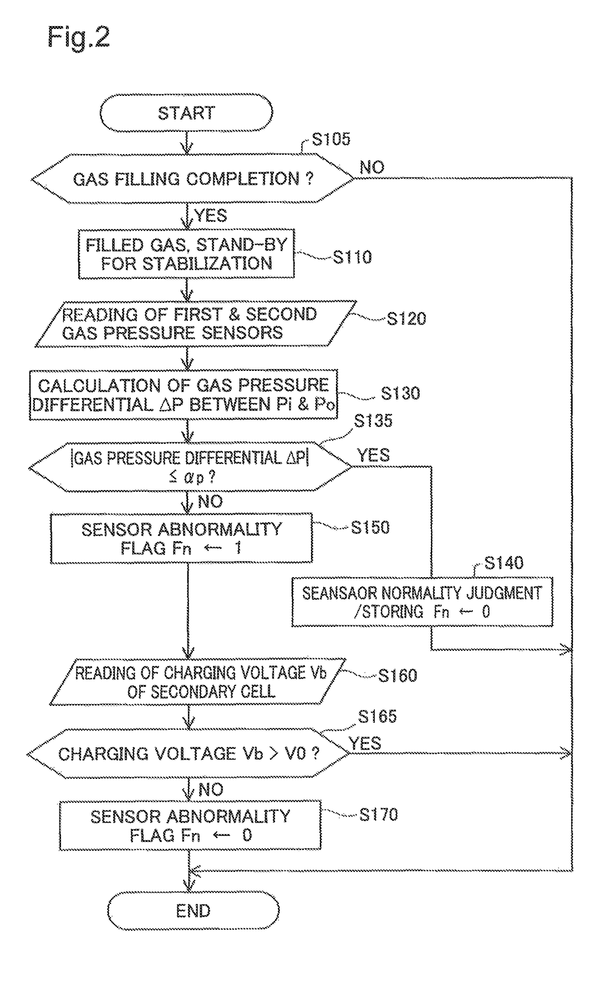
[0057]The fuel cell system 10 of the second embodiment described above does not make any judgment on the output itself using the sensor output of the second gas pressure sensor 132 that detects the gas pressure of the hydrogen gas tank during the gas supply due to impossibility of ensuring reliability for the output of the pressure sensor. Therefore, the fuel cell system 10 of the present embodiment is made not to provide an output evaluation with lower reliability. Instead, the fuel cell system 10 of the present embodiment carries out an output evaluation using the sensor output of the second gas pressure sensor 132 that detects the was pressure of the hydrogen gas tank 110 during the gas supply under a situation where there is no output abnormality derived from a low driving voltage, thus enabling to avoid deterioration of reliability in the output evaluation.

third embodiment

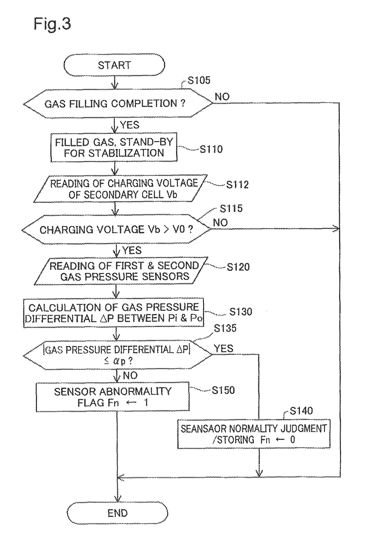
[0058]FIG. 4 is a flow chart showing an output evaluation process of the pressure sensor according to the The present embodiment is characterized by the sequential use of the hydrogen gas tanks 110f and 110r for supplying gas to the fuel cell 100. For the convenience of description, it is assumed that the gas filling is performed for the hydrogen gas tanks 110f and 110r at the same time, and after the gas filling, the hydrogen gas tank 110f is primarily used for gas supply to the fuel cell 100. Subsequently, when the amount of gas in the hydrogen gas tank 110f drops down to a half level, for example, as the vehicle continues to run, the gas is supplied to the fuel cell 100 from the hydrogen gas tank 110r in lieu of the hydrogen gas tank 110f, and thereafter the gas supply is provided from both of the gas tanks.

[0059]As shown in the output evaluation process of the present embodiment in FIG. 4, a judgment is made whether the gas filling is complete or not (Step S105) as has been don...


PUM

PropertyMeasurementUnit
pressureaaaaaaaaaa
electric poweraaaaaaaaaa
gas pressureaaaaaaaaaa

Abstract

This tank device comprises a fuel gas tank that stores fuel gas to be supplied to a gas consuming device, a first pressure sensor that detects the gas pressure when the fuel gas tank is filled with gas, a second pressure sensor that detects the pressure of the fuel gas supplied from the fuel gas tank to the gas consuming device, and a sensor output evaluation unit. The sensor output evaluation unit determines the gas pressure differential between the gas pressure detected by the first pressure sensor when the fuel gas tanks is filled with gas and the gas pressure detected by the second pressure sensor when the fuel gas is first supplied from the fuel gas tank to the gas consuming device after the gas filling, makes a judgment that there is not an output abnormality is any of the first and second pressure sensors if the gas pressure differential is within a given threshold value, and makes a judgement that there is an output abnormality in either of the first and second pressure sensors if the gas pressure differential is beyond the given threshold value.

Description

CROSS-REFERENCE TO RELATED APPLICATION[0001]The present application claims priority from Japanese application P2014-217125 filed on Oct. 24, 2014, the content of which is hereby incorporated by reference into this application.BACKGROUND[0002]Field[0003]The present invention relates to a tank device, a vehicle, and a method for evaluating an output of a pressure sensor.[0004]Related Art[0005]In supplying gas stored in a gas tank to a gas consuming device, the tank device detects the pressure of the supplied gas by a pressure sensor. As one example of each a gas consuming device, a fuel cell is cited. When fuel gas, or hydrogen gas, is supplied from the gas tank to the fuel cell, the gas pressure of the gas tank is reduced and adjusted to a given supply pressure by a pressure regulator such as a decompression valve. Then, a failure evaluation method is proposed whereby the gas pressure of the gas tank, which is on the primary side of the pressure regulator, and the gas supply pressure...

Claims


Application Information

Patent Timeline
Patent Type & Authority Patents(United States)
IPC IPC(8): G01N33/22G01N33/00G01L13/00B60L11/18
CPCG01N33/225B60L11/1838G01L13/00G01N33/0031B60L11/1898Y02T90/34H01M8/04686H01M8/04992B60L3/0053Y02T10/7072B60L53/60B60L50/72B60L58/32Y02T90/12Y02T90/40Y02T10/70Y02E60/50Y02E60/32B60K15/03006B60K6/32G01F9/00G01L19/00G01K13/00Y02T90/14Y02T90/16
Inventor SAITO, HIROMU
Owner TOYOTA JIDOSHA KK
Why Eureka
Try Eureka