
Stereoscopic image display device

a display device and stereoscopic image technology, applied in the field of stereoscopic image display devices, can solve the problems of affecting the accuracy of the image, and the resolution of the 3d image is more than that of the 2d image, so as to prevent the damage to the image and reduce the power consumption of the 3d image

Inactive Publication Date: 2018-08-28
SAMSUNG DISPLAY CO LTD
View PDF24 Cites 1 Cited by
  • Summary
  • Abstract
  • Description
  • Claims
  • Application Information

AI Technical Summary

Benefits of technology

[0012]Embodiments of the present disclosure can provide a structure which may optimize light distribution in a display device depending on a user position to enable a user to more easily perceive a 3D image.
[0013]Embodiments of the present disclosure can provide an autostereoscopic 3D image display device structure capable of extending a viewing distance from a display device while maintaining resolution and luminance equivalent to a 2D image.

Problems solved by technology

A method using only a lenticular lens or a parallax barrier may implement a 3D image, but is affected by issues such as resolution deterioration, moiré patterns, etc.
One issue in existing display devices having a 2D image / 3D image conversion structure is that the resolution of 3D image deteriorates more than that of the 2D image.
However, most autostereoscopic 3D structures are characterized in that a 3D image may only be perceived at a specific distance from the display device, and it can be challenging for a user to find that specific distance.

Method used


Image

  • Stereoscopic image display device
  • Stereoscopic image display device
  • Stereoscopic image display device

Examples


Embodiment Construction

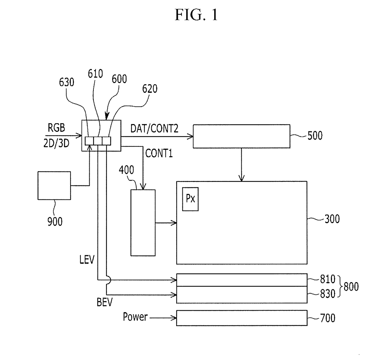
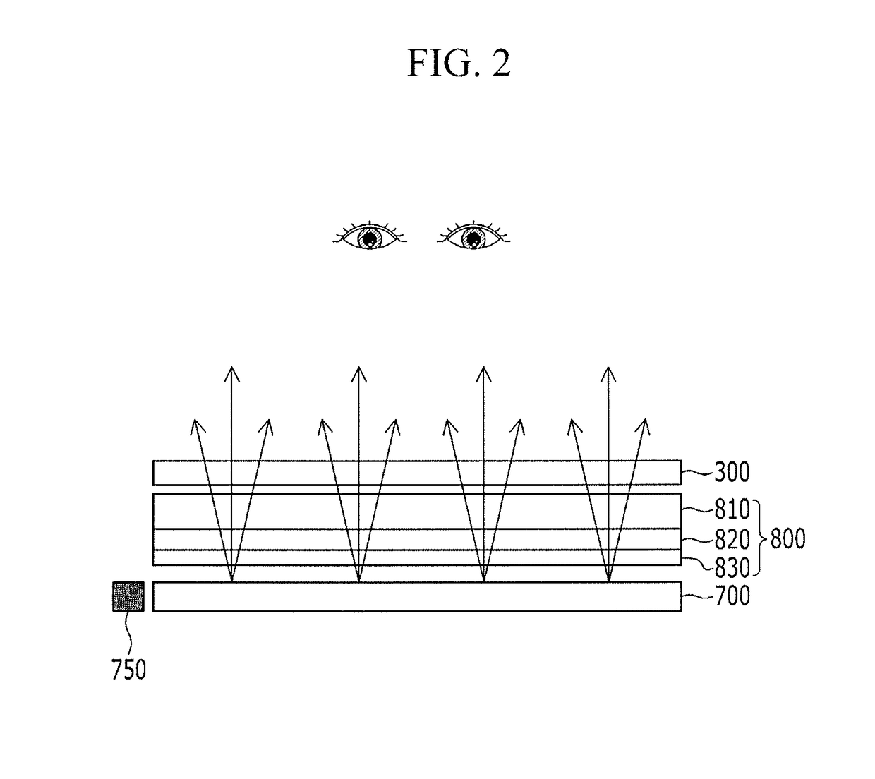
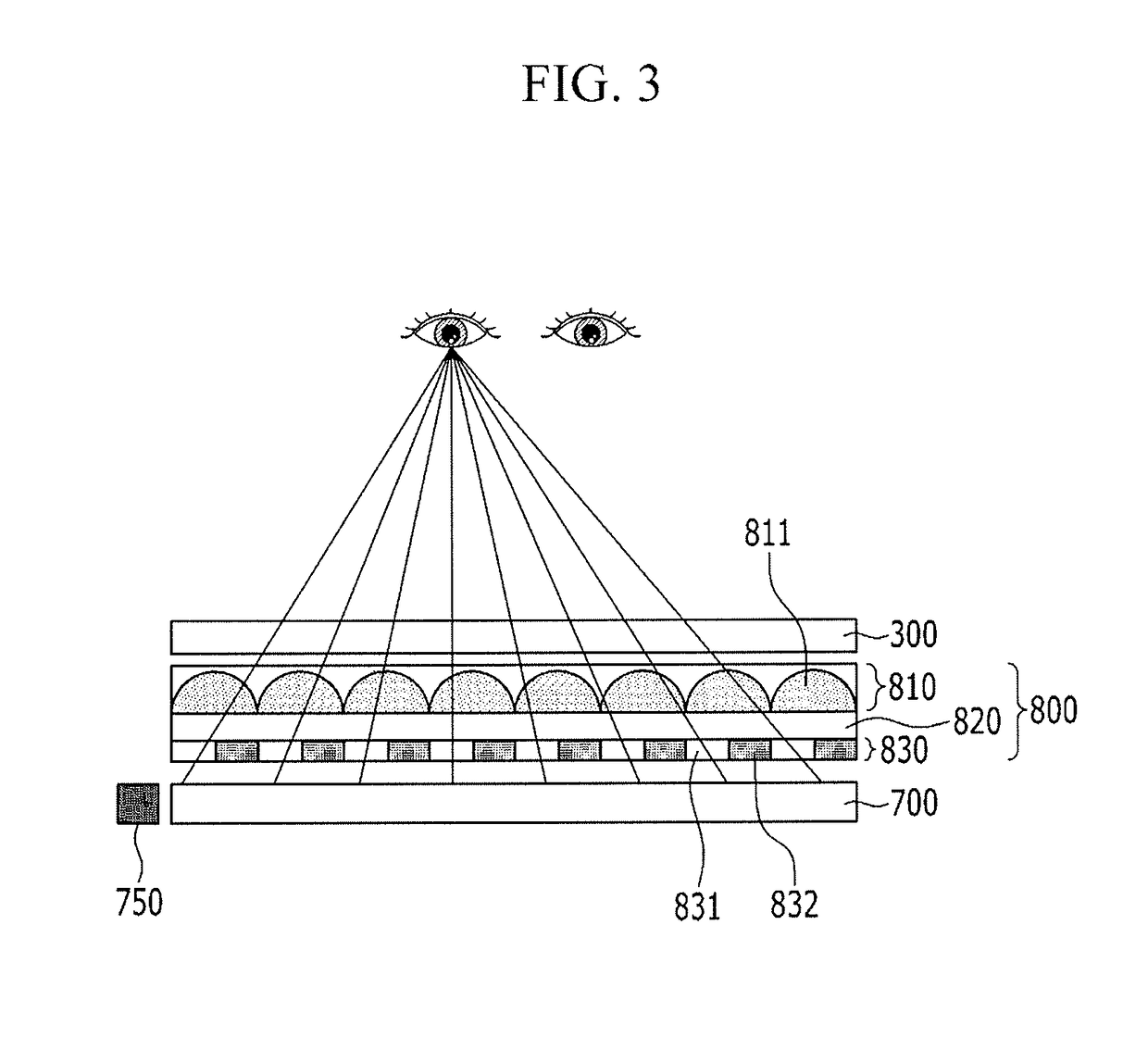
[0057]Hereinafter, the present disclosure will be described more fully with reference to the accompanying drawings, in which exemplary embodiments of the disclosure are shown. As those skilled in the art would realize, the described embodiments may be modified in various different ways, all without departing from the spirit or scope of the present disclosure.

[0058]It is to be noted that the accompanying drawings are schematically illustrated and are not illustrated to a scale. Further, the same structures, elements, or parts which are illustrated in at least two drawings may be denoted by the same reference numerals, which is used to indicate similar features. The mention that any portion is present “over” or “on” another portion means that any portion may be directly formed on another portion or a third portion may be interposed between one portion and another portion.

[0059]Hereinafter, a stereoscopic image display device according to an exemplary embodiment will be described in de...


PUM

PropertyMeasurementUnit
refractive indexaaaaaaaaaa
widthaaaaaaaaaa
light transmitting widthaaaaaaaaaa

Abstract

A stereoscopic image display device includes a display panel for displaying an image; a liquid crystal lens layer positioned under the display panel that refracts light like a lenticular lens depending on application of power, the liquid crystal lens layer including a plurality of nano polymer-dispersed liquid crystals (PDLC); a barrier layer integrally formed under the liquid crystal lens layer that has a light transmitting position and width that change depending on a power applying position, the barrier layer including a plurality of reflective PDLCs; and a backlight unit (BLU) positioned under the barrier layer that is configured to provide light to the display panel.

Description

CROSS REFERENCE TO RELATED APPLICATIONS[0001]This application claims priority from Korean Patent Application No. 10-2014-0173323 filed in the Korean Intellectual Property Office on Dec. 4, 2014, and all the benefits accruing therefrom, the contents of which are herein incorporated by reference in their entirety.BACKGROUND[0002]1. Technical Field[0003]Embodiments of the present disclosure are generally directed to a stereoscopic image display device, and more particularly, to a stereoscopic image display device capable of performing a mutual conversion between a 2 dimension (2D) image and a 3D image.[0004]2. Discussion of the Related Art[0005]Among various technology developments, a demand for and development of a stereoscopic image display which does not use glasses has continuously progressed.[0006]To display a 3D image without using glasses in an existing flat display device, binocular disparity is used, in which the left and right eyes of an observer view different images. The me...

Claims


Application Information

Patent Timeline
Patent Type & Authority Patents(United States)
IPC IPC(8): G02B27/22G02F1/1334G02F1/137G02F1/1343G02B30/27G02B30/31
CPCH04N13/305H04N13/322H04N13/398G02F1/134309G02B27/2214G02F1/137G02F1/1334H04N13/373G02B30/27G02B30/31H04N13/30
Inventor KIM, YOUNG CHANPARK, CHEUL JIN
Owner SAMSUNG DISPLAY CO LTD
Learn More