Image display controller

a technology of image display and control system, applied in the direction of television system, pedestrian/occupant safety arrangement, instruments, etc., can solve the problems of inability to assemble such objects that are originally seen as different shapes into identical objects driver feels a sense of incompatibility, etc., and achieve the effect of effective execution

a technology of image display and control system, applied in the direction of television system, pedestrian/occupant safety arrangement, instruments, etc., can solve the problems of inability to assemble such objects that are originally seen as different shapes into identical objects driver feels a sense of incompatibility, etc., and achieve the effect of effective execution

US20050012685A1Active Publication Date: 2005-01-20PANASONIC CORP

Image

  • Image display controller
  • Image display controller
  • Image display controller

Examples


Embodiment Construction

[0024] An embodiment of an image display controlling system of the present invention will be explained with reference to FIG. 1 to FIG. 3 hereinafter.

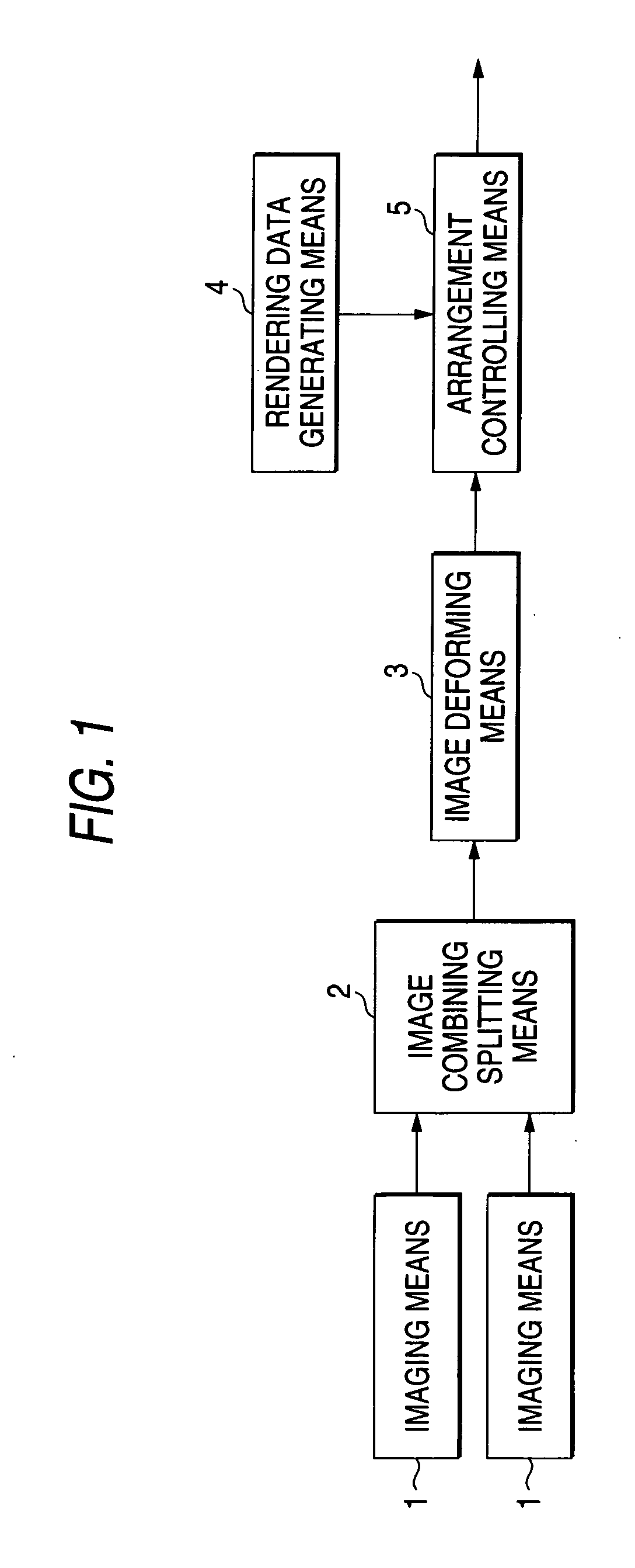
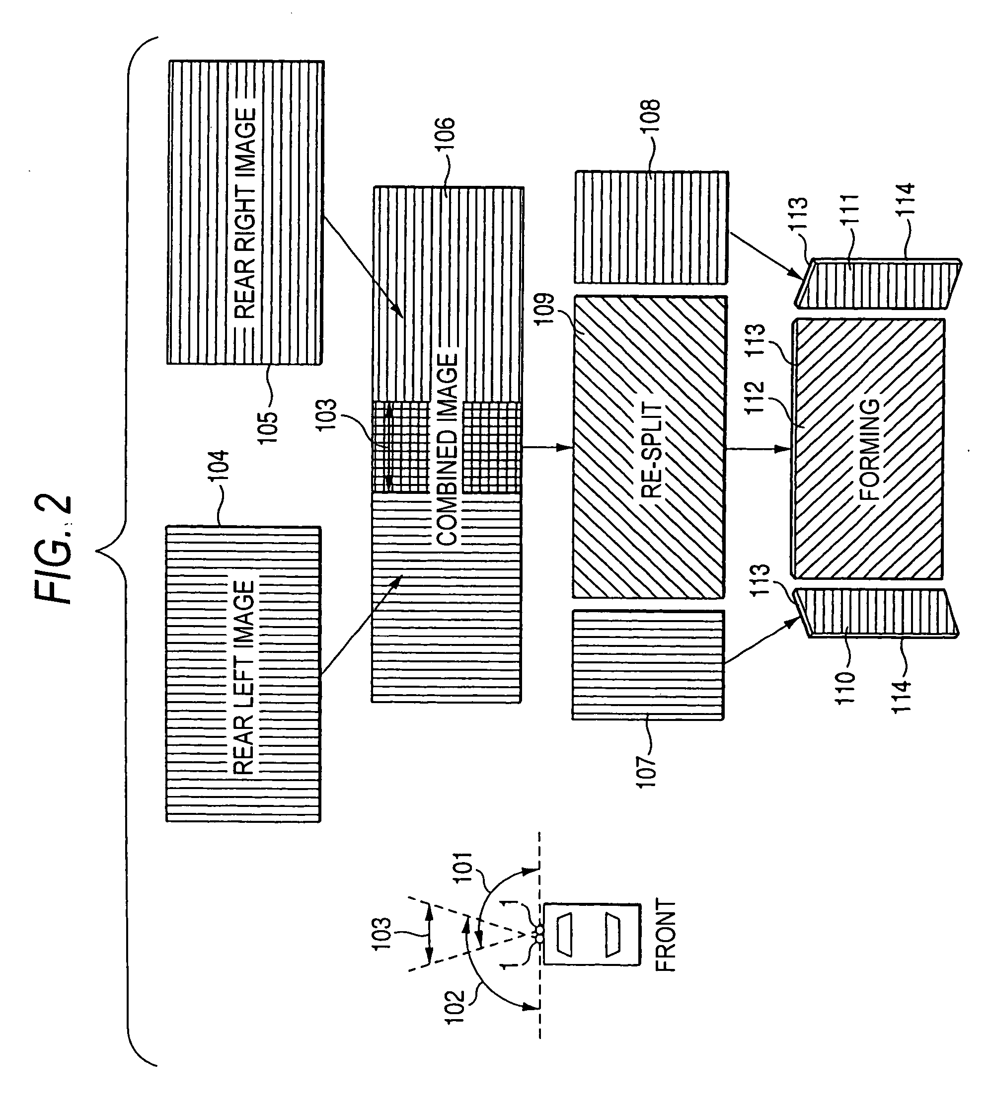
[0025]FIG. 1 is a configurative block diagram of an image display controlling system the present invention. FIG. 2 is an explanatory view showing a flow of operations required until the images picked up by imaging means are deformed and displayed. FIG. 3 is a view showing an actual display example in the image display controlling system of the present invention.

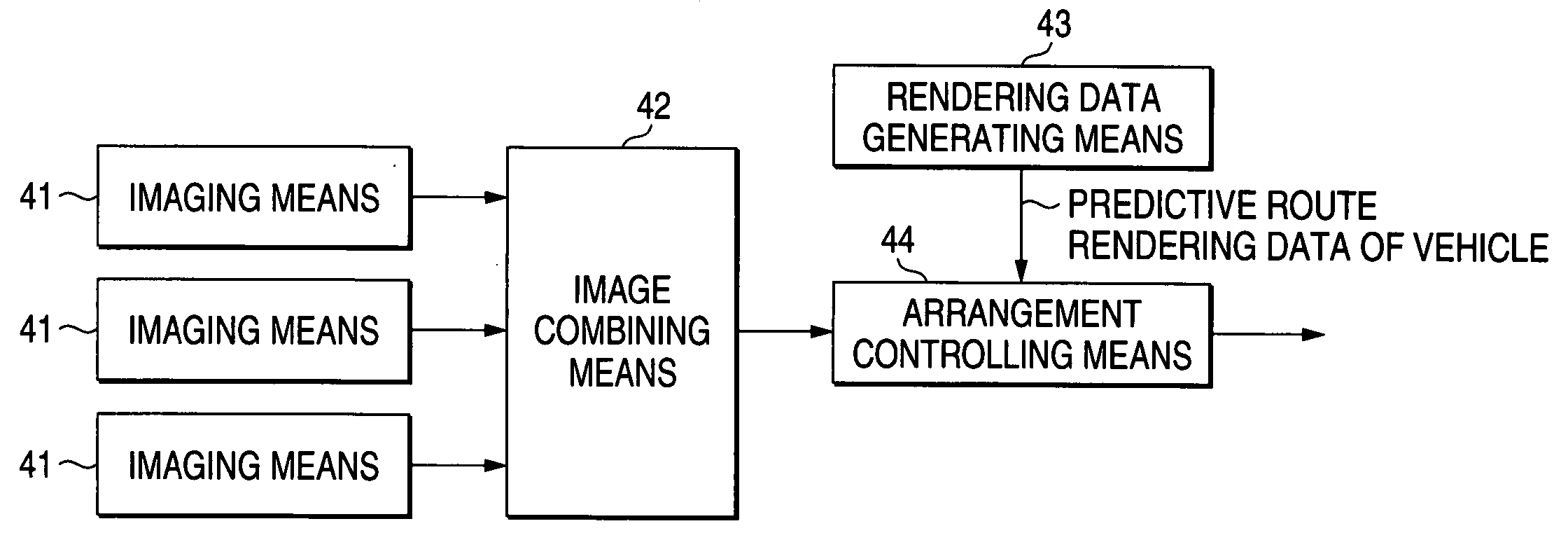
[0026] The image display controlling system of the present invention has an image combining splitting means 2 for splitting picked-up image input from imaging means 1, which pick up surrounding images of a vehicle, into a plurality of images, an image deforming means 3 for performing different deforming processes for each of the images respectively, and an arrangement controlling means 5 for arranging a plurality of images at predetermined positions and displaying them.

[0027]...


PUM


Abstract

An image display controlling system of the present invention has an image combining splitting means (2) for splitting a picked-up image input from an imaging means (1), which picks up surrounding images of a vehicle, into a plurality of images, an image deforming means (3) for executing a different deforming process to the plurality of images respectively, and an arrangement controlling means (5) for arranging the plurality of images at predetermined positions and displaying the images. According to this configuration, a wide-range image having a horizontal angle of view of 180 degree is separated into a rear center image positioned at a center of the image and side images separated from the center like a vanity with three mirrors, and a sense of depth is provided by distorting and deforming intentionally the side images in contrast to the rear center image such that the side images can look as if the side images are just looked at.

Description

TECHNICAL FIELD [0001] The present invention relates to an image display controlling system which picks up images in a wide range including a driver's blind spot on the rear side and the front side of a vehicle by using cameras, and displays the images explicitly. BACKGROUND ART [0002] In a prior art, a system described in JP-A-10-257482, for example, etc. are known as the image display controlling system. FIG. 4 is a configurative block diagram of an image display controlling system in a prior art. In the image display controlling system in the prior art, imaging means 41 are installed into a vehicle, and a plurality of picked-up images output from the imaging means 41 are input into an image combining means 42 to combine therein. The vehicle predictive route locus data generated by a rendering data generating means 43 to assist the driving, etc. are superposed with a combined image which was combined by the image combining means 42, then input into an arrangement controlling means...

Claims


Application Information

Patent Timeline
20 Jan 2005
Publication
US20050012685A1
IPC
B60R21/00; B60R1/00; G06T1/00; G06T3/00; G09G5/00; G09G5/36; G09G5/377; G09G5/397; H04N7/18
CPC
B60R1/00; B60R2300/105; B60R2300/302; B60R2300/305; B60R2300/306; H04N7/181; G09G5/377; G09G5/397
Inventors
OKADA, TSUYOSHI; MIZUSAWA, KAZUFUMI