Computed tomography system having cooling system

a computed tomography and cooling system technology, applied in tomography, x-ray tube cooling, application, etc., can solve the problem of reducing the durability of the entire ct system

Inactive Publication Date: 2018-09-04
SAMSUNG ELECTRONICS CO LTD
View PDF20 Cites 2 Cited by
  • Summary
  • Abstract
  • Description
  • Claims
  • Application Information

AI Technical Summary

Problems solved by technology

However, the individual fans of the respective parts and an exhaust fan of the gantry unit of the CT system may cause noise and vibration in the overall CT system, and thus, may reduce durability of the entire CT system.

Method used


Image

  • Computed tomography system having cooling system
  • Computed tomography system having cooling system
  • Computed tomography system having cooling system

Examples


Embodiment Construction

[0059]A computed tomography (CT) system according to an exemplary embodiment will be described with reference to the accompanying drawings. In the drawings, like reference numerals refer to like elements throughout the specification and elements having like reference numerals may be formed of the same material. Also, in the drawings, thicknesses of layers and regions may be exaggerated for clarity of the layers and regions.

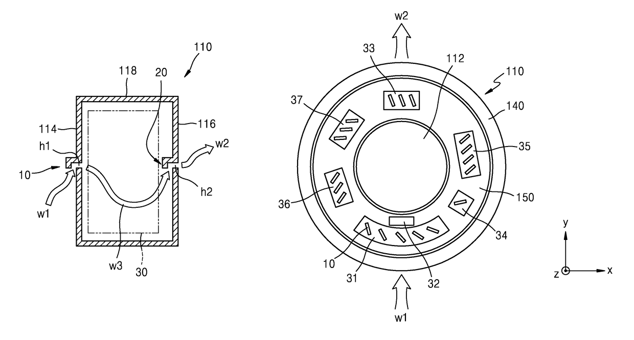
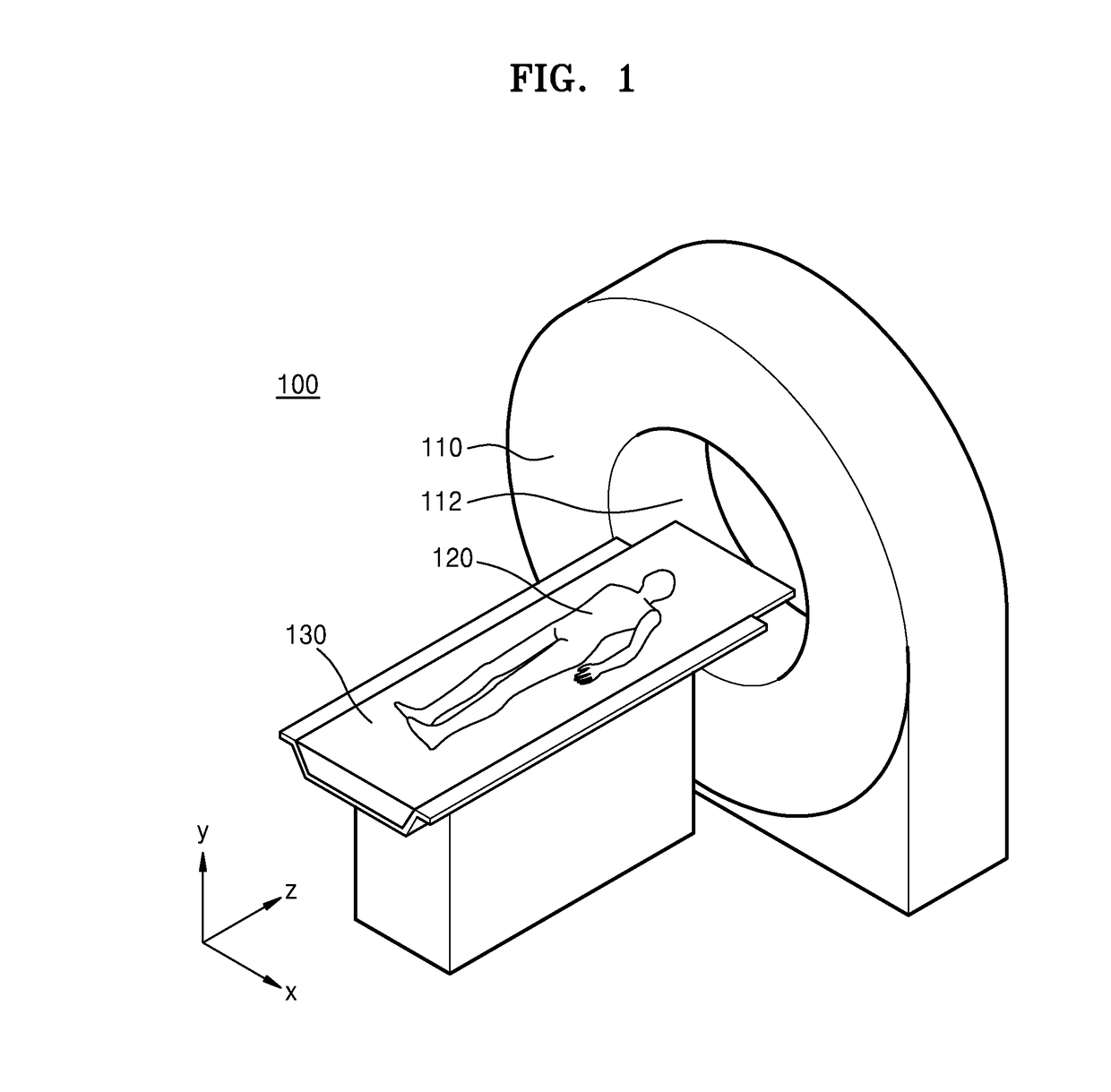
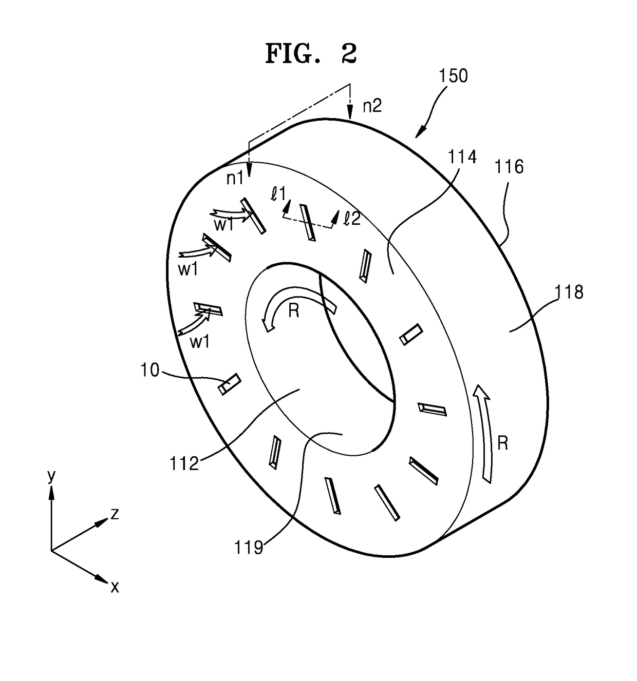
[0060]FIG. 1 is a schematic perspective view of a CT system 100 according to an exemplary embodiment. FIG. 2 is a perspective view illustrating a first surface 114 of a rotor 150 of a CT system 100 according to an exemplary embodiment. FIG. 3 is a perspective view illustrating the second surface 116 of the rotor 150 of a CT system 100 according to an exemplary embodiment.

[0061]Referring to FIG. 1, the CT system 100 according to an exemplary embodiment may include a gantry unit 110 and a table 130 that may move a subject 120 to be inspected. The gantry unit 110 may...


PUM


Abstract

A computed tomography (CT) system having a cooling system includes: a gantry unit, including a rotor and an assembly component; an intake provided on a first surface of the rotor; and an outtake provided on a second surface opposite to the first surface of the rotor; wherein the gantry unit is cooled by air moving through the intake and the outtake due to a rotation force or a centrifugal force generated by a rotation movement of the rotor.

Description

CROSS-REFERENCE TO RELATED APPLICATION[0001]This application claims priority from Korean Patent Application No. 10-2015-0113372, filed on Aug. 11, 2015, in the Korean Intellectual Property Office, the disclosure of which is incorporated herein by reference in its entirety.BACKGROUND1. Field[0002]Apparatuses and methods consistent with exemplary embodiments relate to computed tomography (CT) systems, and more particularly, to CT systems having a cooling system and methods of cooling the same.2. Description of the Related Art[0003]With advances in medical technology, various methods have been developed to obtain information about an internal body of a subject, and in particular, a tomography system is widely used to obtain such information. A representative tomography system is a computed tomography (CT) system.[0004]A CT system is an apparatus that irradiates X-rays onto a subject at various angles, measures the X-rays that have transmitted through the subject, and displays an image ...

Claims


Application Information

Patent Timeline
Patent Type & Authority Patents(United States)
IPC IPC(8): H05G1/02A61B6/03A61B6/00
CPCA61B6/4488H05G1/025A61B6/035A61B2560/0406H01J2237/002H01J2235/127H01J2235/1208H01J2235/1216H01J2235/1225H01J2235/12A61B6/032A61B6/4208A61B6/44A61B6/4429A61B6/52A61B6/5258
Inventor YUN, ALEXANDERKIM, SUNG-KISEONG, IL
Owner SAMSUNG ELECTRONICS CO LTD
Why Eureka
Try Eureka