
Compressed-air system having a safety function and method for operating such a compressed-air system

a technology of compressed air and function, which is applied in the direction of fluid handling accessories, container filling methods, fluid pressure actuators, etc., can solve the problems of inability the failure of both channels or both working valves, and the interruption of the load operation to check the functional capability of the working valves

Active Publication Date: 2018-09-04
FESTO AG & CO KG
View PDF39 Cites 1 Cited by
  • Summary
  • Abstract
  • Description
  • Claims
  • Application Information

AI Technical Summary

Benefits of technology

The invention aims to allow for two-channel venting without interrupting the operation of the load. This guarantees reliable venting even if one of the valves fails, while also providing a redundant venting possibility. A separating device allows for individual examination of each valve without affecting the compressed-air supply. This allows for testing the complete venting function of both valves without interrupting operation.

Problems solved by technology

This is against a background in which a wide variety of defect scenarios are conceivable and known, which can lead to a breakdown of both channels or both working valves.
An example here would be the sticking of the valve member gasket with the resultant impossibility to switch over the working valve or a rupture of the return spring with the resultant blocking of the current switching position of the working valve.
This problem is particularly pronounced in compressed-air systems which are used to operate loads which are switched on and have to be supplied with compressed air for long periods.
Here, though, the additional problem arises that an interruption in the operation of the load to check the functional capability of the working valves is not really acceptable, because this is associated with an interruption in the process performed by the load.
In this way only slight venting takes place, causing only minor disruption to the load.
In sensitive loads, however, such a partial stroke test can also result in an error message and a possible operational interruption.
Furthermore, the partial stroke examination does not provide any indication that the working valve is actually in a position to fully switch over to the venting position if necessary.

Method used


Image

  • Compressed-air system having a safety function and method for operating such a compressed-air system
  • Compressed-air system having a safety function and method for operating such a compressed-air system
  • Compressed-air system having a safety function and method for operating such a compressed-air system

Examples


Embodiment Construction

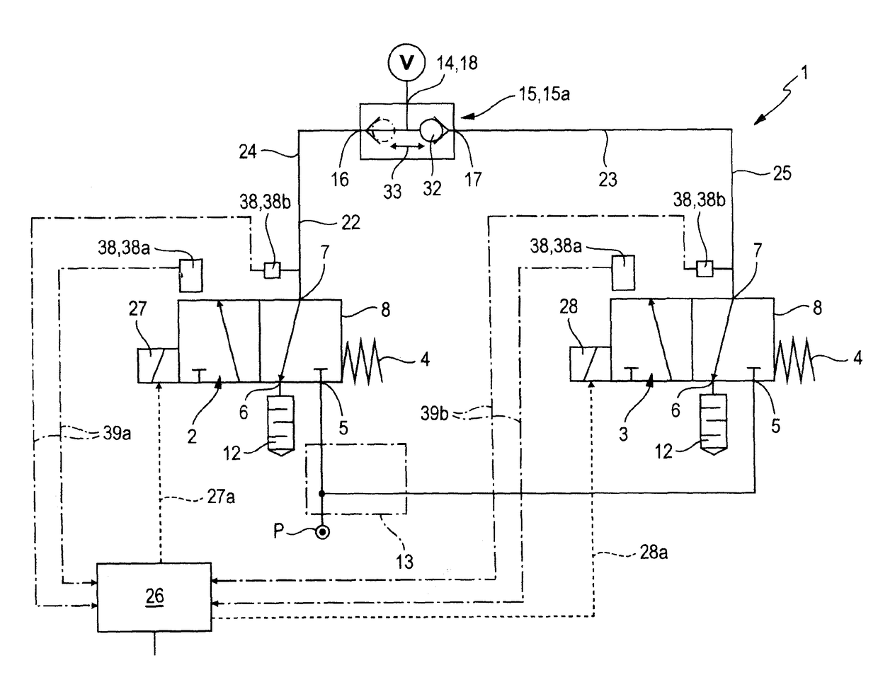
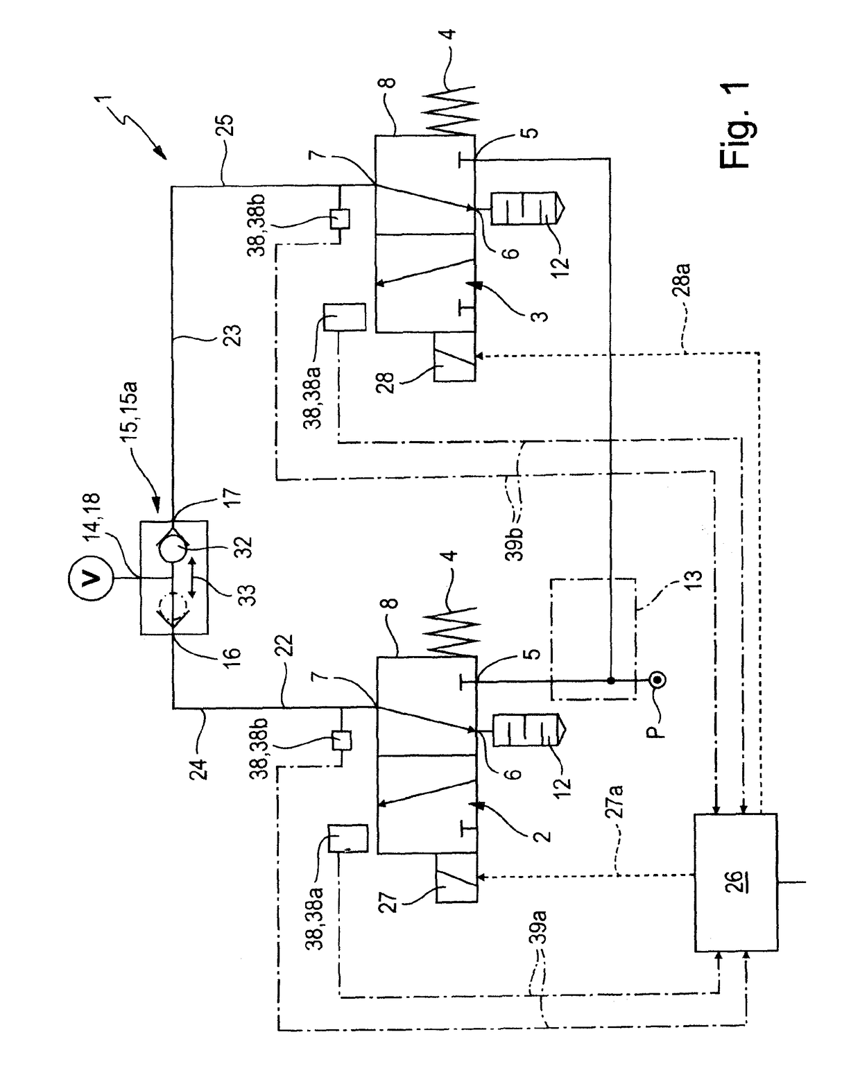
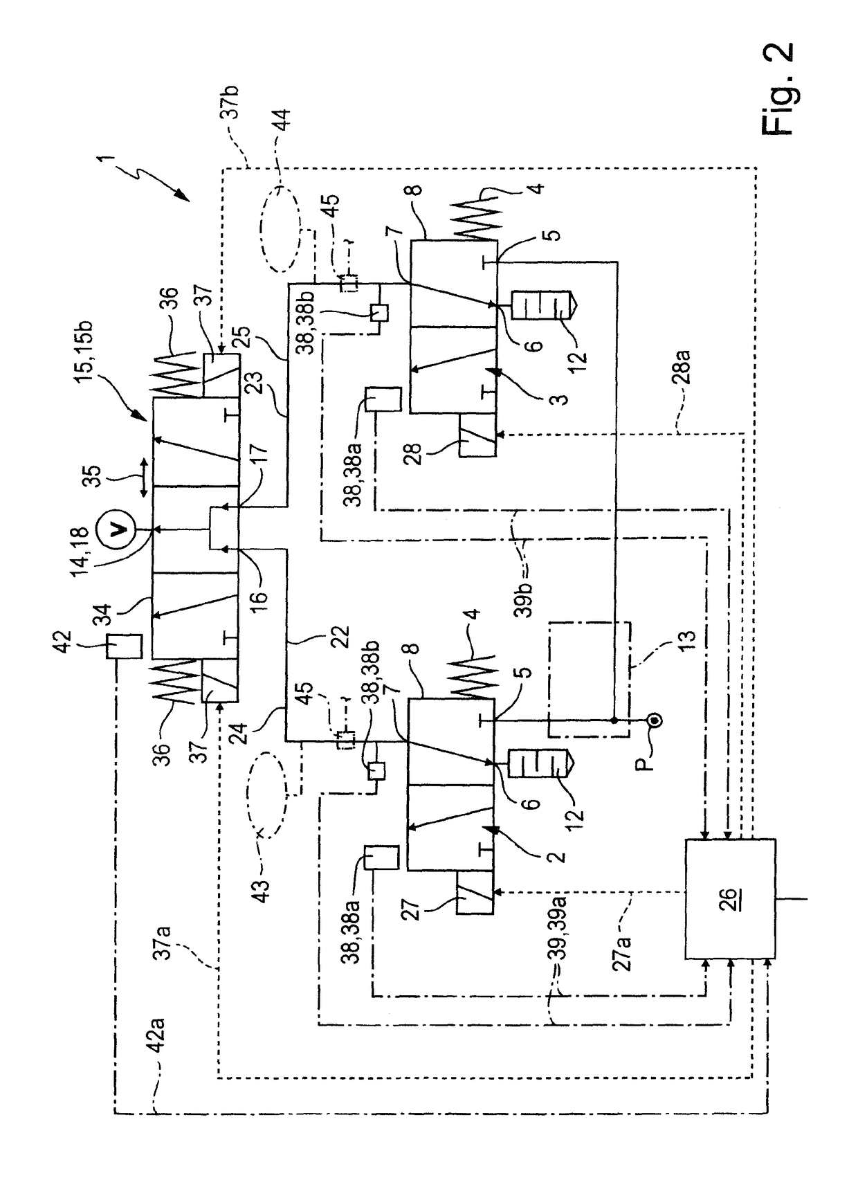
[0038]The circuits shown in the drawing implement in each case a safety-related compressed-air system 1 with what is known as a two-channel design. The compressed-air systems 1 are advantageously designed so that in any operating situation they can switch off on a two-channel basis in order to guarantee the reliable venting of a connected load V. Even during a test procedure to test the functional capability of the valve technology, at no time can the compressed-air system lapse into single-channel mode.

[0039]The following description relates jointly to all illustrated compressed-air systems 1, unless stated to the contrary in an individual case.

[0040]The compressed-air system 1 in the exemplary embodiments is built as what is known as an on-off valve, with the help of which the compressed air supply to a load V can be optionally switched on or off. In the switched-on state the compressed-air system 1 ensures aeration of the load V, thus a supply of compressed air, which the load V ...


PUM


Abstract

A compressed-air system having a safety function and a method for operating such a compressed-air system. The compressed-air system contains two working valves, which each can selectively assume an aerating position that aerates a load and a venting position that vents the load. Both working valves are redundantly connected on the output side to the load by means of a separating device. The separating device allows one or the other of the working valves to be separated, while the aeration of the load is maintained, in order to subject the one or the other working valve to an examination of the switching function of the one or the other working valve.

Description

[0001]This application claims priority based on an International Application filed under the Patent Cooperation Treaty, PCT / EP2015 / 000512, filed Mar. 6, 2015, which claims priority to DE102014006357.7, filed Apr. 30, 2014.BACKGROUND OF THE INVENTION[0002]The invention relates to a compressed-air system having a safety function, with a first and a second working valve, each of which has a working connection and a venting connection connected or connectable to the atmosphere, wherein the two working connections are connected in parallel fluid communication with one and the same load output of the compressed-air system which load output is connected or connectable to a load, wherein each working valve is switchable into a venting position connecting its working connection with its venting connection and wherein the two working valves can simultaneously assume their venting position. The invention also relates to a method for operating such a compressed-air system.[0003]A compressed-air...

Claims


Application Information

Patent Timeline
Patent Type & Authority Patents(United States)
IPC IPC(8): F15B20/00F15B19/00F17C13/04
CPCF15B20/008F15B19/00F17C13/04F15B2211/3052F15B2211/3056F17C2250/0626F15B2211/634F15B2211/6313F15B2211/855F15B2211/8855F15B2211/30565
Inventor SAUER, JOSEFVARGAS, ALEXANDERJAINCZYK, MANFREDROOS, ECKARDBEIL, PETER
Owner FESTO AG & CO KG
Learn More