Rod-shaped force transducer with simplified adjustment

a force transducer and simplified technology, applied in the field of rod-shaped force transducers, can solve the problems of falsification of measurement results, cost or time-consuming, and difficulty in carrying out rotational compensation, and achieve the effect of high linearity and accurate measurement results

Inactive Publication Date: 2018-09-04
HOTTINGER BRUEL & KJAER GMBH
View PDF26 Cites 3 Cited by
  • Summary
  • Abstract
  • Description
  • Claims
  • Application Information

AI Technical Summary

Benefits of technology

[0011]In view of the above, it is an object of at least one embodiment of the invention, to provide a force transducer, for which no mechanical compensation by material removal and/or electrical compensation i

Problems solved by technology

Therefore carrying out the rotational compensation is costly or time-consuming.
Even after such a rotational compensation, the danger of a falsification of the measurem

Method used


Image

  • Rod-shaped force transducer with simplified adjustment
  • Rod-shaped force transducer with simplified adjustment
  • Rod-shaped force transducer with simplified adjustment

Examples


Embodiment Construction

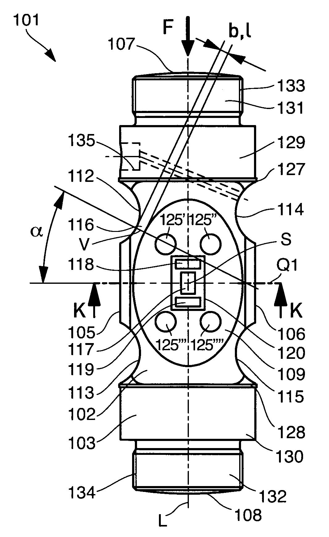
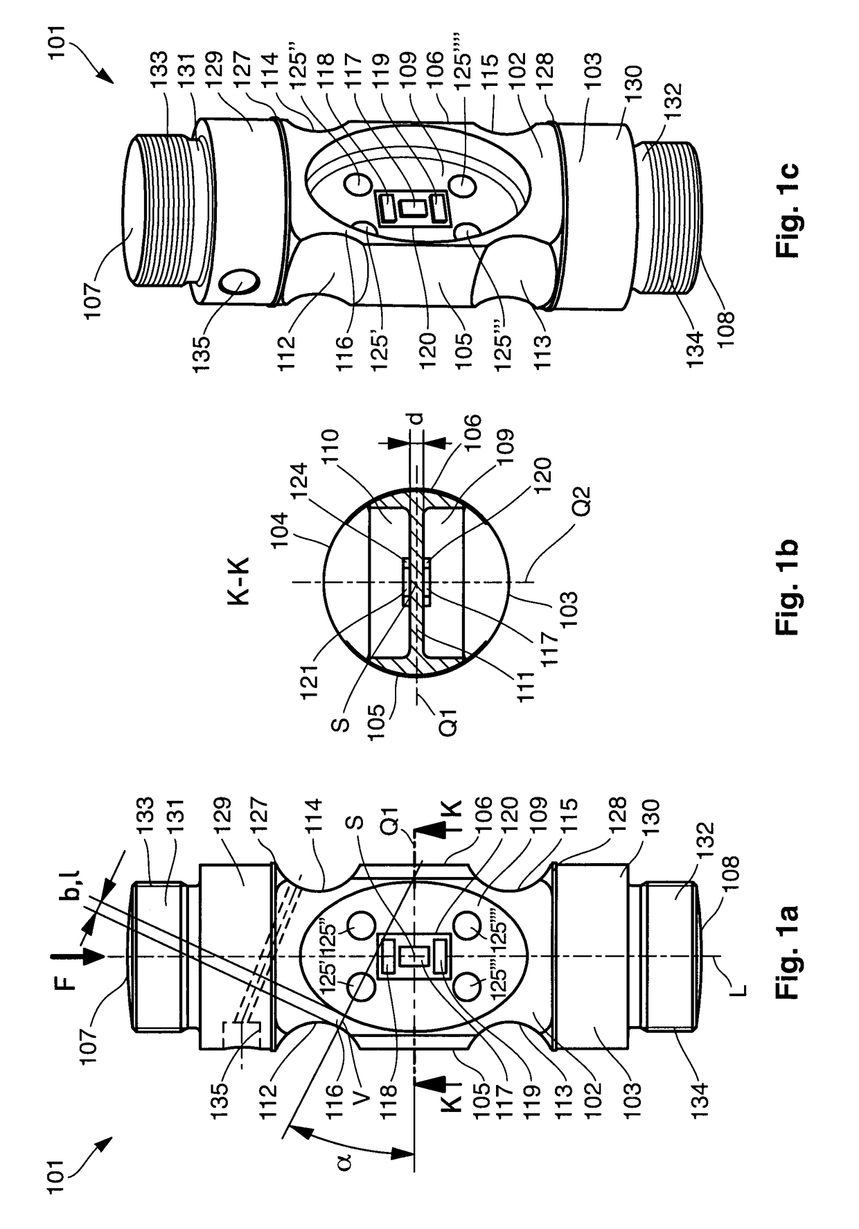
[0041]FIG. 1a shows a front view of the force transducer 101 according to the first example embodiment, FIG. 1b shows a section K-K through the force transducer 101, and FIG. 1c shows a perspective view of the force transducer 101.

[0042]The force transducer 101 encompasses a rod-shaped deformation body 102 of a material such as, for example, steel, titanium, aluminum or beryllium copper. It can be machined out of a rod with a circular, quadratic or other cross-section, e.g. from a piece of round steel or square steel stock. The following description starts from the assumption that the deformation body is based on a cylindrical rod and itself has a cylindrical basic shape as shown in the drawings. However, other variants are also possible, in which the deformation body 102 can then also comprise more sides than the sides described in the following.

[0043]The deformation body 102 comprises a central longitudinal axis L, which extends vertically in the front view illustrated in FIG. 1a....


PUM


Abstract

A force transducer for measuring compression and/or tension forces includes a rod-shaped deformation body and at least four strain transducers applied on the deformation body and configured for measuring a longitudinal strain and a transverse strain of the deformation body. Front and rear elongate recesses are provided on the front and rear sides of the deformation body at an intersection point between a central longitudinal axis and a central transverse axis of the deformation body. Left and right upper indentations and left and right lower indentations are provided on the deformation body respectively at the four quadrants bounded by the axes. An angle between the central transverse axis and a shortest connecting line between the front elongate recess and the left upper indentation is at least 17° and at most 29°.

Description

FIELD OF THE INVENTION[0001]The present invention relates to a rod-shaped force transducer, which can be adjusted or compensated more easily than known rod-shaped force transducers.BACKGROUND INFORMATION[0002]Rod-shaped force transducers are known, in which a longitudinal strain and a transverse strain of a rod-shaped measuring body or deformation body are detected, respectively with the aid of strain transducers applied on the deformation body. From the electrical signals produced by the strain transducers, based thereon a force to be measured can be determined. When they are provided for the construction of weighing scales, such force transducers are also referred to as load cells or weighing cells.[0003]For a rod-shaped force transducer of the described type, a costly or time-consuming compensation adjustment is necessary, which is also referred to as a rotation compensation. Thereby, tolerances of the deformation body or of the strain transducers that arise due to the production...

Claims


Application Information

Patent Timeline
IPC IPC(8): G01L1/22G01G3/14
CPCG01L1/22G01L1/2231G01L1/2218G01G3/14
Inventor JAEGER, ANDREASWILL, HEINZ-RONALDSCHLACHTER, WERNER
Owner HOTTINGER BRUEL & KJAER GMBH
Why Eureka
Try Eureka