X-ray imaging system and method with a real-time controllable 3D X-ray attenuator

a three-dimensional, real-time control technology, applied in the direction of instruments, diaphragms/collimeters, radiation diagnostic diaphragms, etc., can solve the problems of reducing image quality, reducing x-ray radiation dose, and contradicting two requirements, so as to reduce x-ray radiation dose and improve image quality

Active Publication Date: 2018-09-04
GENERAL ELECTRIC CO
View PDF6 Cites 2 Cited by
  • Summary
  • Abstract
  • Description
  • Claims
  • Application Information

AI Technical Summary

Benefits of technology

[0007]In accordance with an aspect of the present disclosure, an X-ray imaging system comprising an X-ray source that emits X-ray radiation; an X-ray collimator positioned adjacent to the X-ray source; a real-time controllable 3D X-ray attenuator; a digital X-ray detector; and a system controller coupled to the X-ray source, the X-ray collimator, the real-time controllable 3D X-ray attenuator, and the digital X-ray detector for controlling the real-time controllable 3D X-ray attenuator to reduce X-ray radiation dose and improve image quality.

Problems solved by technology

However, these two requirements contradict each other.
Generally, for a given X-ray imaging system and method, higher image quality requires higher X-ray radiation dose and lower X-ray radiation dose yields lower image quality.
Existing X-ray imaging systems and methods determine X-ray techniques based on either the contrast-to-noise ratio (CNR) or the signal-to-noise ratio (SNR) of the densest or thickest portion of a patient's anatomy or subject being imaged, which means that the X-ray radiation dose in all other regions of the anatomy is unnecessarily higher than it requires, which not only results in unnecessarily higher X-ray radiation dose to the patient, but lower image contrast as well.
This results in patient anatomy receiving only the necessary X-ray radiation dose, resulting in an overall lower radiation dose.

Method used


Image

  • X-ray imaging system and method with a real-time controllable 3D X-ray attenuator
  • X-ray imaging system and method with a real-time controllable 3D X-ray attenuator
  • X-ray imaging system and method with a real-time controllable 3D X-ray attenuator

Examples


Embodiment Construction

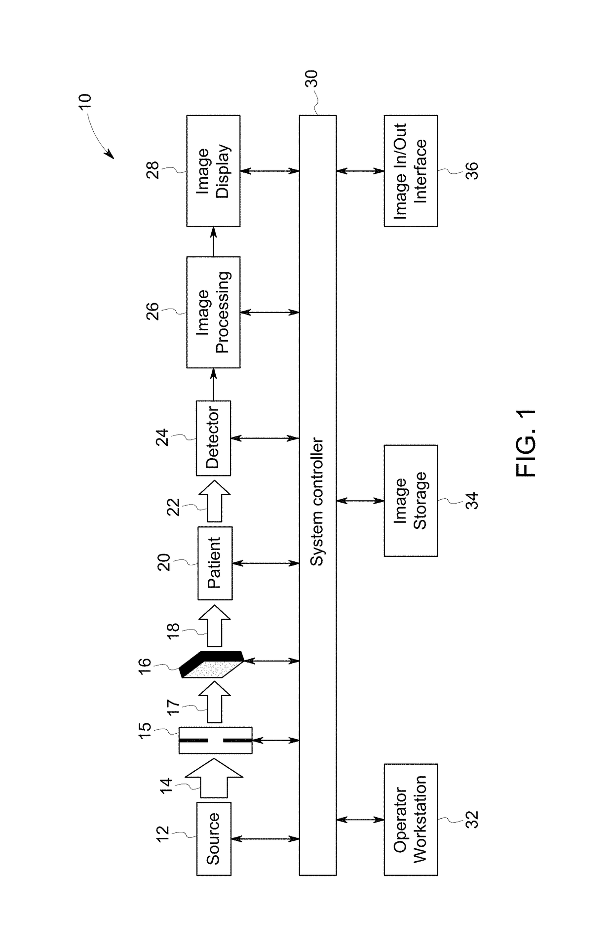
[0020]Referring generally to FIG. 1, an X-ray imaging system is represented and referenced generally by reference numeral 10. In the illustrated embodiment, the X-ray imaging system 10, as adapted, is a digital X-ray imaging system. The X-ray imaging system 10 is designed both to acquire image data and to process the image data for display in accordance with the present technique. Throughout the following discussion, however, while basic and background information is provided on the digital X-ray imaging system used in medical diagnostic applications, it should be born in mind that aspects of the present techniques may be applied to X-ray imaging systems, used in different settings (e.g., projection X-ray imaging, computed tomography imaging, tomosynthesis imaging, fluoroscopic imaging, mammographic imaging, radiographic imaging, etc.) and for different purposes (e.g., parcel, baggage, vehicle and component inspection, etc.).

[0021]FIG. 1 illustrates a block diagram of an exemplary e...


PUM


Abstract

An X-ray imaging system including an X-ray source, an X-ray collimator, a real-time controllable 3D X-ray attenuator, a digital X-ray detector, and a system controller coupled to the X-ray radiation source, the collimator, the real-time controllable 3D X-ray attenuator, and the digital X-ray detector for controlling the real-time controllable 3D X-ray attenuator to reduce X-ray radiation dose and improve image quality. The real-time controllable 3D X-ray attenuator includes a top panel, a bottom panel, at least one sidewall joining the top panel to the bottom panel, an open area between the top panel, bottom panel, and at least one 2D pixel array coupled to at least one of the top panel and the bottom panel, the at least one 2D pixel array having a plurality of pixels of thin film electric coils and switching thin film field-effect transistors, wherein the open area is at least partially filled with a mixture of ferromagnetic material and medium X-ray attenuation material.

Description

CROSS-REFERENCE TO RELATED APPLICATIONS[0001]This application claims the benefit of U.S. Provisional Patent Application No. 62 / 098,821, filed on Dec. 31, 2014, the entirety of which is incorporated herein by reference.BACKGROUND[0002]This disclosure relates generally to X-ray imaging systems and methods, and more particularly to X-ray imaging system and method with a real-time controllable three-dimensional (3D) X-ray attenuator that filters an X-ray beam and generates an X-ray beam with a variable radiation dose according to a two-dimensional (2D) X-ray image intensity map.[0003]Better image quality and the lower X-ray radiation dose to a patient or subject being imaged are always the top requirement on any X-ray imaging system and method. However, these two requirements contradict each other. Generally, for a given X-ray imaging system and method, higher image quality requires higher X-ray radiation dose and lower X-ray radiation dose yields lower image quality.[0004]Existing X-ra...

Claims


Application Information

Patent Timeline
Patent Type & Authority Patents(United States)
IPC IPC(8): A61B6/06G21K1/04G21K1/10A61B6/00
CPCG21K1/04A61B6/06A61B6/488G21K1/10A61B2560/0266G01N2223/316G21K1/046A61B6/542
Inventor LIU, JAMES
Owner GENERAL ELECTRIC CO
Why Eureka
Try Eureka