Fuel cell system having valve module between fuel cell stack and humidifier

a technology of fuel cell and humidifier, which is applied in the direction of transportation hydrogen technology, electric generators, transportation fuel cell technology, etc., can solve the problems of increasing the concentration of hydrogen and a fire risk, affecting the performance and durability and the inability to meet global technical regulations (gtrs), so as to prevent the performance degradation and durability degradation of the fuel cell stack

Active Publication Date: 2018-09-04
HYUNDAI MOTOR CO LTD
View PDF15 Cites 0 Cited by
  • Summary
  • Abstract
  • Description
  • Claims
  • Application Information

AI Technical Summary

Benefits of technology

[0032]An aspect of the present inventive concept provides a safety fuel cell system satisfying Global Technical Regulations (GTRs) in an operation range thereof irrespective of a degraded state of a fuel cell stack without a risk of fire.
[0033]Another aspect of the present inventive concept provides a fuel cell system preventing performance degradation and durability degradation of a fuel cell stack caused by air left after shutdown of the fuel cell system.

Problems solved by technology

When such air is left within the system, performance degradation and durability degradation of the fuel cell stack 10 may occur.
In this case, hydrogen is pushed into the exhaust line 37 without being mixed with air, thus, increasing the concentration of hydrogen and a fire risk.
Furthermore, it may be impossible to meet Global Technical Regulations (GTRs).
However, such hydrogen concentration reduction has limitations.
Furthermore, it may be impossible to meet the desired regulations.
In this case, a portion of water discharged from the fuel cell stack 10 is fed back to the fuel cell stack 10, and thus, efficient water removal may not be achieved.
When residual water in the fuel cell stack 10 freezes in winter, a start-up time taken for the cold start may increase or a start-up failure may occur.

Method used


Image

  • Fuel cell system having valve module between fuel cell stack and humidifier
  • Fuel cell system having valve module between fuel cell stack and humidifier
  • Fuel cell system having valve module between fuel cell stack and humidifier

Examples


Embodiment Construction

[0056]Hereinafter reference will now be made in detail to various embodiments of the present inventive concept, examples of which are illustrated in the accompanying drawings and described below. While the invention will be described in conjunction with exemplary embodiments, it will be understood that present description is not intended to limit the invention to those exemplary embodiments. On the contrary, the invention is intended to cover not only the exemplary embodiments, but also various alternatives, modifications, equivalents, and other embodiments, which may be included within the spirit and scope of the invention as defined by the appended claims.

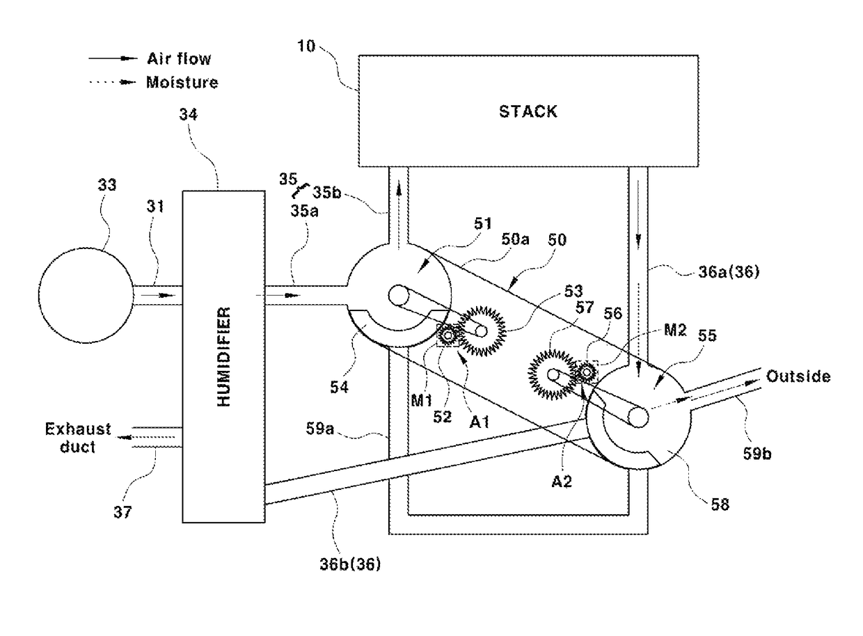
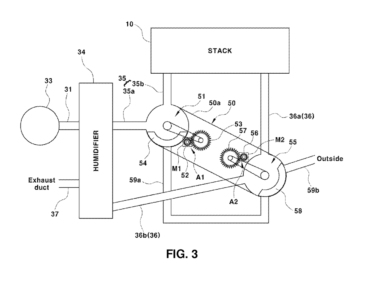
[0057]FIG. 3 is a view illustrating a fuel cell system according to an embodiment of the present inventive concept in which a unified valve module is installed.

[0058]As illustrated in FIG. 3, a unified valve module 50 is installed between an air supply line 35 and a stack cathode-side exhaust line 36, which connect a fuel cell st...


PUM

PropertyMeasurementUnit
temperatureaaaaaaaaaa
timeaaaaaaaaaa

Abstract

A fuel cell system includes an air supply unit for supplying air containing oxygen to a fuel cell stack. A humidifier humidifies the supplied air. An air supply line is connected between a cathode inlet of the fuel cell stack and the humidifier to supply the humidified air to the fuel cell stack. A cathode-side exhaust line is connected between a cathode outlet of the fuel cell stack and the humidifier to supply a cathode exhaust gas discharged from a cathode of the fuel cell stack to the humidifier for humidification in the humidifier. A unified valve module includes a bypass line connected between the air supply line and the cathode-side exhaust line and an outward discharge port discharging the cathode exhaust gas to outside, and controls a gas flow between the humidifier and the fuel cell stack and between the bypass line and the outward discharge port.

Description

CROSS-REFERENCE TO RELATED APPLICATION[0001]This application claims under 35 U.S.C. § 119(a) the benefit of priority to Korean Patent Application No. 10-2015-0068670 filed on May 18, 2015, the entire contents of which are incorporated herein by reference.TECHNICAL FIELD[0002]The present disclosure relates to a fuel cell system. More particularly, the present disclosure relates to a safe fuel cell system satisfying Global Technical Regulations (GTRs) in an operation range thereof without a risk of fire.BACKGROUND[0003]A fuel cell system for an environmentally friendly hydrogen fuel cell vehicle includes a fuel cell stack generating electrical energy through an electrical chemical reaction of reactive gas. A hydrogen supplier supplies fuel gas, that is, hydrogen, to the fuel cell stack. An air supplier supplies air containing oxidizing gas, that is, oxygen. A heat and water management system controls an operation temperature of the fuel cell stack, and performs a water management func...

Claims


Application Information

Patent Timeline
Patent Type & Authority Patents(United States)
IPC IPC(8): H01M8/06H01M8/04228H01M8/04119H01M8/04223H01M8/04225
CPCH01M8/04253H01M8/04126H01M8/04225H01M8/04231H01M8/04228Y02T90/32H01M2250/20H01M8/04156Y02E60/50Y02T90/40
Inventor LEE, JUNG JAEYOON, SUNG GONEKIM, SAE HOON
Owner HYUNDAI MOTOR CO LTD
Why Eureka
Try Eureka