Image pickup apparatus

a technology of image pickup and sensitivity, which is applied in the direction of exposure control, instruments, television systems, etc., can solve the problems of poor light use efficiency, low sensitivity, and poor resolution, and achieve the effect of preventing image quality degradation and sensitivity lowering, and extending the exposure time period

Active Publication Date: 2008-09-04
FUJIFILM CORP
View PDF9 Cites 36 Cited by
  • Summary
  • Abstract
  • Description
  • Claims
  • Application Information

AI Technical Summary

Benefits of technology

[0014]It is therefore an object of the invention to provide an image pickup apparatus capable of preventing image quality degradation and sensitivity lowering caused by a charge stored in a charge storage section in any other time period than an exposure time period and extending the exposure time period.

Problems solved by technology

However, with the color solid-state image pickup device with the color filters arranged as a tessellated pattern, if the color filters are primary color filters, about two thirds of incidence light are absorbed in the color filters and thus the light use efficiency is poor and the sensitivity is low; this is a problem.
Since a color signal only of one color can be obtained in each light reception section, the resolution is also poor and particularly a false color is conspicuous; this is also a problem.
However, a considerable time may be required until the carrier generated in the photoelectric conversion layer arrives at an electrode connected to the charge storage section and thus a carrier not moved to the charge storage section although it was generated in the photoelectric conversion layer during the exposure time period is stored in the charge storage section after reset as a residual image component.
If the residual image component exists in the charge storage section, the potential of the electrode connected to the charge storage section rises and thus the bias voltage applied to the photoelectric conversion layer relatively lowers and a problem of lowering the carrier transport performance and making poor sensitivity can also occur.
However, in so doing, the potential of the charge storage section fluctuates between the reset timings shown in FIG. 9 and thus meanwhile the force pulling out the residual image component in the photoelectric conversion layer to the electrode weakens.

Method used


Image

  • Image pickup apparatus
  • Image pickup apparatus
  • Image pickup apparatus

Examples


first embodiment

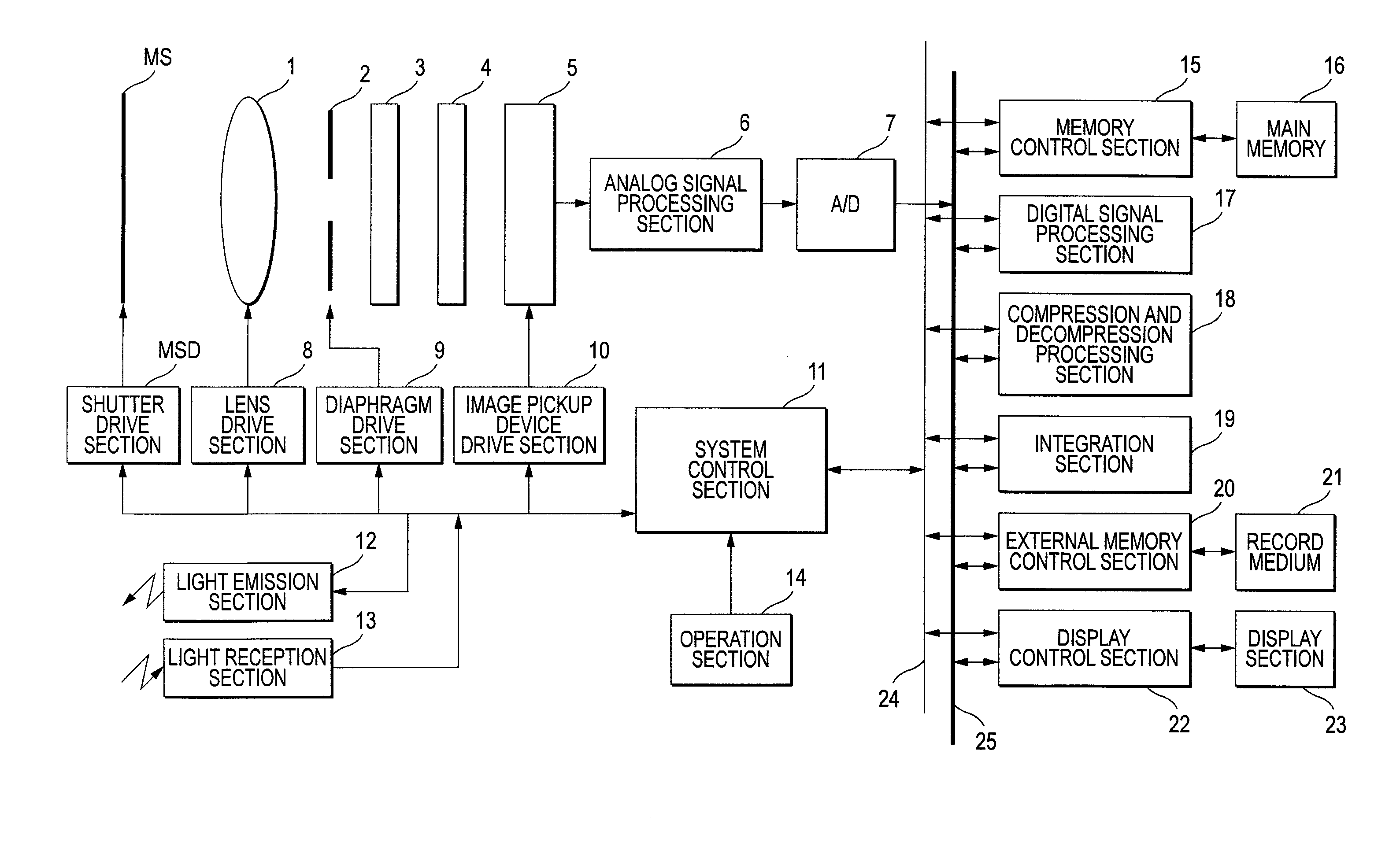
[0031]FIG. 1 is a diagram to show the schematic configuration of a digital camera as an example of an image pickup apparatus to describe a first embodiment of the invention.

[0032]An image pickup system of the digital camera shown in the figure includes a mechanical shutter MS, a taking lens 1, an image pickup device 5, and a diaphragm 2, an infrared cut filter 3, and an optical low-pass filter 4 provided between the taking lens 1 and the image pickup device 5.

[0033]A system control section 11 for controlling the whole of an electric control system of the digital camera controls a flash light emission section 12 and a light reception section 13, controls a lens drive section 8 to adjust the position of the taking lens 1 to a focus position and make zoom adjustment, controls the aperture amount of the diaphragm 2 through a diaphragm drive section 9 to make light exposure adjustment, and performs opening / closing control of the mechanical shutter MS through a shutter drive section MSD. ...

second embodiment

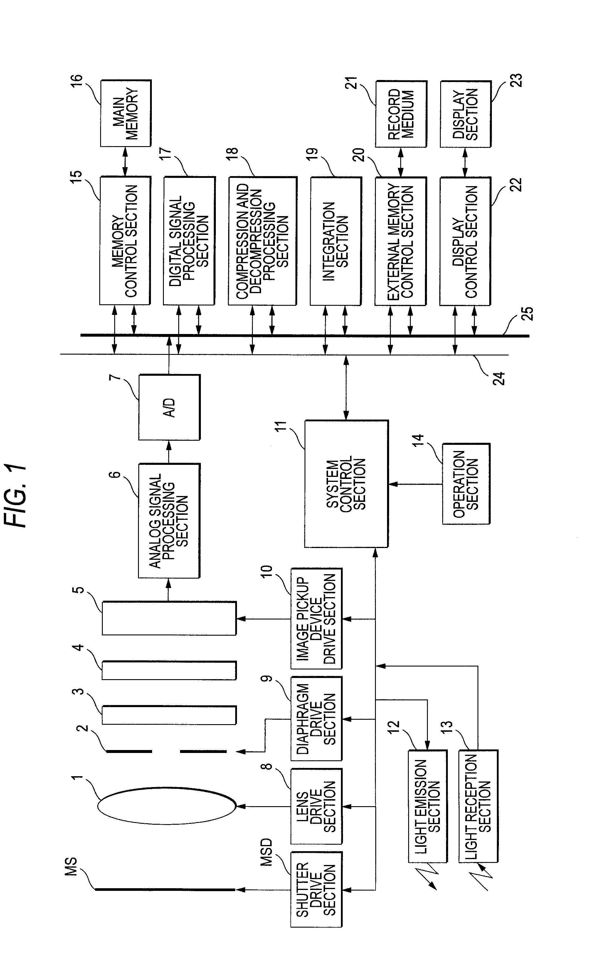
[0061]In the first embodiment, keeping the potential of the lower electrode 56 constant is accomplished by controlling the applying time of the reset voltage; in a second embodiment of the invention, it is accomplished by devising the circuit configuration of signal read section 54. The general configuration of a digital camera described in the second embodiment and the configuration of an image pickup device installed in the digital camera are similar to those in FIGS. 1 and 2. The second embodiment differs from the first embodiment only in the configuration of the signal read section 54 shown in FIG. 2 and the function of image pickup device drive section 10. The configuration of the signal read section 54 in the second embodiment will be discussed below:

[0062]FIG. 5 is an equivalent circuit diagram of an image pickup device installed in a digital camera of the second embodiment of the invention. Components identical with or corresponding to those in FIG. 2 are denoted by the same...

third embodiment

[0068]FIG. 6 is an equivalent circuit diagram of an image pickup device installed in a digital camera of a third embodiment of the invention. Components identical with or corresponding to those in FIG. 5 are denoted by the same reference numerals in FIG. 6.

[0069]The image pickup device shown in FIG. 6 has a configuration wherein a series circuit made up of a capacitor 70 and a switch 71 in parallel to a capacitor 53 is provided between the inverting input terminal and the output terminal of the inverting amplifier 66 of the image pickup device shown in FIG. 5. The switch 71 is connected at one end to the inverting input terminal of the inverting amplifier 66 and at an opposite end to one end of the capacitor 70. The output terminal of the inverting amplifier 66 is connected to an opposite end of the capacitor 70.

[0070]A system control section 11 of the digital camera determines whether or not the electrode stored in the capacity 53 exceeds the capacitance of the capacity 53 by pre-p...


PUM


Abstract

A lower electrode, a photoelectric conversion layer, and an upper electrode are stacked in order above a semiconductor substrate, and a charge storage section that stores charge generated in the photoelectric conversion layer is connected to the lower electrode. The charge stored in the charge storage section is swept away by a charge sweeping away section for a given time from the endpoint of exposure. The given time is a time taken until the residual image charge existing in the photoelectric conversion layer at the exposure end point time is sufficiently discharged to the outside of the photoelectric conversion layer in a state in which the same bias as that at the exposure start time point is applied to the photoelectric conversion layer.

Description

BACKGROUND OF THE INVENTION[0001]1. Field of the Invention[0002]This invention relates to an image pickup apparatus having an image pickup device having a photoelectric conversion element stacked above a semiconductor substrate and a charge storage section formed in the semiconductor substrate for storing a charge generated in the photoelectric conversion element for outputting a signal responsive to the charge stored in the charge storage section to the outside.[0003]2. Description of the Related Art[0004]In a single-plate color solid-state image pickup device represented by an image sensor of CCD type or CMOS type, three or four types of color filters are placed on a light reception section array for executing photoelectric conversion as a tessellated pattern. Accordingly, a color signal corresponding to the color filter is output from each light reception section and the color signals are processed, whereby a color image is generated.[0005]However, with the color solid-state imag...

Claims


Application Information

Patent Timeline
Patent Type & Authority Applications(United States)
IPC IPC(8): H04N5/335
CPCH01L27/14632H01L27/14643H04N5/374H04N5/3696H04N5/335H01L27/1462H01L27/14647H04N25/00H04N25/70H04N25/76
Inventor OTA, MOTOARI
Owner FUJIFILM CORP
Why Eureka
Try Eureka