Variable valve timing controller for internal combustion engine

a timing controller and internal combustion engine technology, applied in electrical control, instruments, couplings, etc., can solve problems such as and achieve the effect of restricting the motor current, preventing durability deterioration and motor malfunction

Active Publication Date: 2008-03-20
DENSO CORP +1
View PDF5 Cites 11 Cited by
  • Summary
  • Abstract
  • Description
  • Claims
  • Application Information

AI Technical Summary

Benefits of technology

[0007] In a case that the state where the deviation of the target motor speed and the actual motor speed does not become small will continue, the restricting action of the motor current can be continued, and it can be possible to restrict the motor...

Problems solved by technology

If it is continued that the deviation is larger than a predetermined value for a long period, there is a possibility that the motor current i...

Method used


Image

  • Variable valve timing controller for internal combustion engine
  • Variable valve timing controller for internal combustion engine
  • Variable valve timing controller for internal combustion engine

Examples


Embodiment Construction

[0018] An embodiment of the present invention will be described hereinafter.

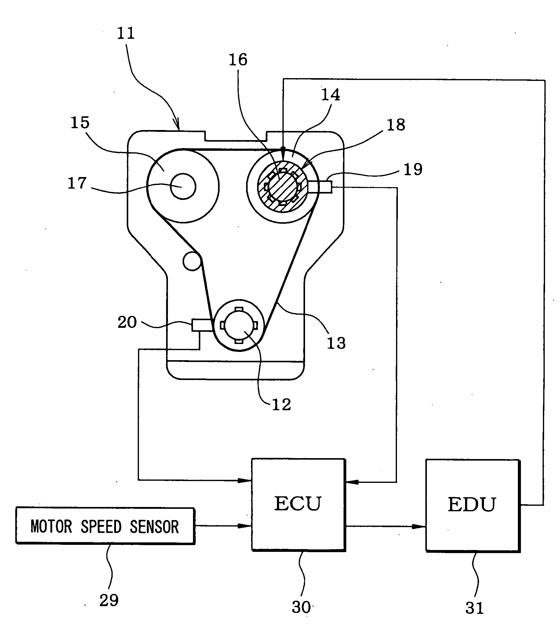
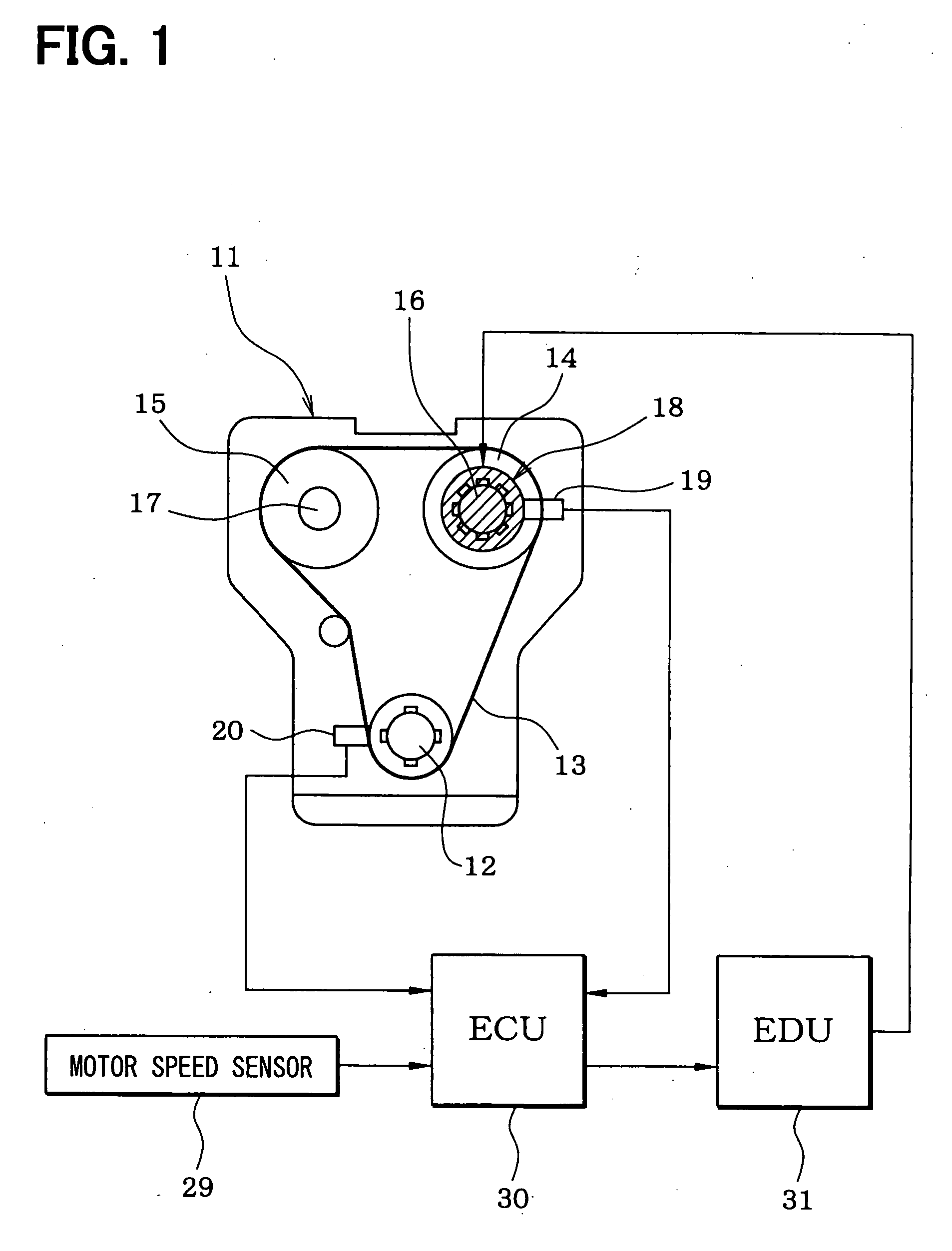
[0019]FIG. 1 schematically shows a whole structure of an engine control system. An internal combustion engine 11, which is referred to as an engine hereinafter, includes a crankshaft 12. A driving force of the crankshaft 12 is transmitted to an intake camshaft 16 and an exhaust camshaft 17 through a timing chain 13 (or a timing belt) and sprockets 14, 15. A variable valve timing controller 18, which includes an electric motor, is coupled to the intake camshaft 16. The variable valve timing controller 18 varies a rotational phase (camshaft phase) of the intake camshaft 16 relative to the crankshaft 12 so that the valve timing of an intake vale (not shown) is adjusted.

[0020] A cam angle sensor 19 is provided around the intake camshaft 16. The cam angle sensor 19 outputs a cam angle signal every predetermined cam angle of the intake camshaft 16. A crank angle sensor 20 is provided around the cranks shaft 12. ...


PUM


Abstract

A motor current (driving current of motor) is estimated based on a target motor speed, an actual motor speed, and an engine speed. When the estimated motor current exceeds the upper limit value equivalent to a heat generation limiting current, the motor current is restricted by restricting a variation (motor speed F/B amount) in target motor speed outputted to an EDU from an ECU. If it is continued that a deviation between the target motor speed and the actual motor speed exceeds a predetermined value, the estimated motor current exceeds this upper limit value and the restricting action of the motor current is continued.

Description

CROSS REFERENCE TO RELATED APPLICATION [0001] This application is based on Japanese Patent Application No. 2006-233282 filed on Aug. 30, 2006, the disclosure of which is incorporated herein by reference. FIELD OF THE INVENTION [0002] The present invention relates to a variable valve timing controller which includes an electric motor as a driving source. A rotation speed of the electric motor is varied to adjust a rotational phase of the camshaft relative to a crankshaft, whereby a valve timing of an intake valve and / or an exhaust valve of an internal combustion engine is adjusted. BACKGROUND OF THE INVENTION [0003] In order to perform electronic control of the variable valve timing control, the variable valve timing controller which has the motor as a source of the drive has been developed. The variable valve timing controller described in JP-2006-70754A (US2006 / 0042578A1) includes a first gear, a second gear, a phase changing gear, and an electric motor. The first gear (outer gear)...

Claims


Application Information

Patent Timeline
IPC IPC(8): F02D28/00
CPCF01L1/352F02D13/02Y02T10/18F02D2041/001F02D35/0007Y02T10/12
Inventor TANAKA, TOSHIKAZUINOUE, MASAOMITAKEMURA, YUUICHIMASHIKI, ZENICHIRO
Owner DENSO CORP
Why Eureka
Try Eureka