Supercharge Your Innovation With Domain-Expert AI Agents!

Electric connector

a technology of electric connectors and connectors, applied in the direction of incorrect coupling prevention, coupling device connection, electrical apparatus, etc., can solve the problems of disabling the removal operation itself, unable to perform the operation of both hands in the narrow space, and unable to enter the inside of the narrow space, so as to prevent damage to each part configuring the connector, avoid plastic deformation of the lock member, and prevent damage

Active Publication Date: 2018-09-04
DAIICHI SEIKO CO LTD
View PDF81 Cites 5 Cited by
  • Summary
  • Abstract
  • Description
  • Claims
  • Application Information

AI Technical Summary

Benefits of technology

The present invention is an electric connector with a lock releasing member that prevents damage to the parts and plastic deformation of the lock member during excessive rotating operation. The lock releasing member has a release operating part that can make reciprocating rotations between an initial position away from the insertion opening and an acting position close to the insertion opening. This allows easy removal of a flat-plate-shaped signal transmission medium with a simple structure. The technical effect of this invention is to improve the reliability and efficiency of the electric connector.

Problems solved by technology

In particular, as described in Japanese Unexamined Patent Application Publication No. 2013-178892 mentioned below, if lock members are arranged at both end portions in a connector longitudinal direction, for example, when the flat-plate-shaped signal transmission medium is removed from the electric connector in a narrow space inside an electrical appliance or the like, it is difficult to perform the operation by both hands in that narrow space.
Also, in the first place, both hands may not be able to enter the inside of the narrow space, thereby disabling the removal operation itself.

Method used


Image

  • Electric connector
  • Electric connector
  • Electric connector

Examples


Embodiment Construction

[0048]In the following, an electric connector according to one embodiment of the present invention is described in detail based on the drawings.

[0049][Entire Structure of Electrical Connector]

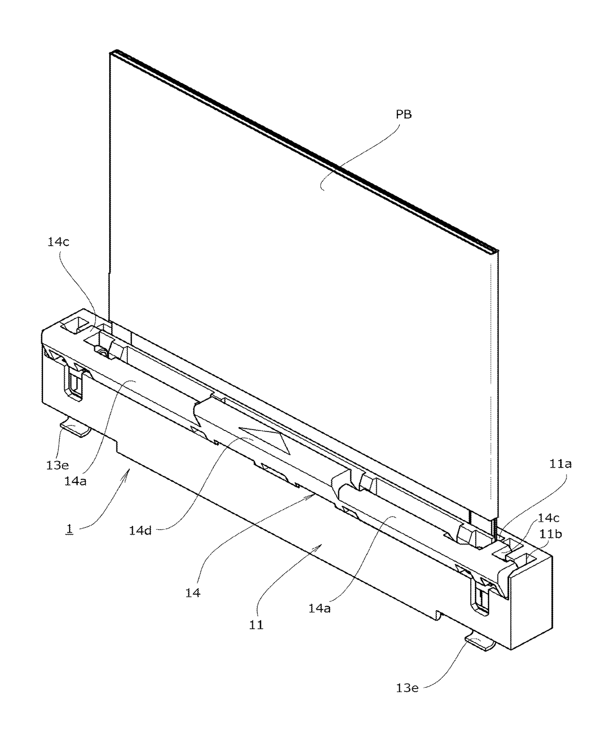
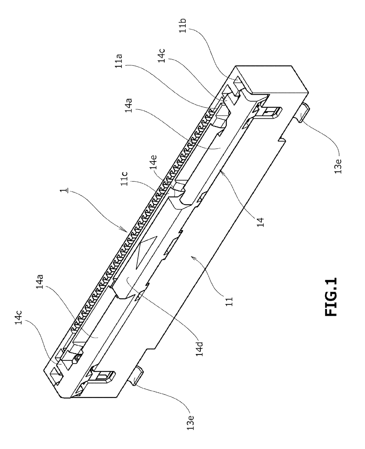
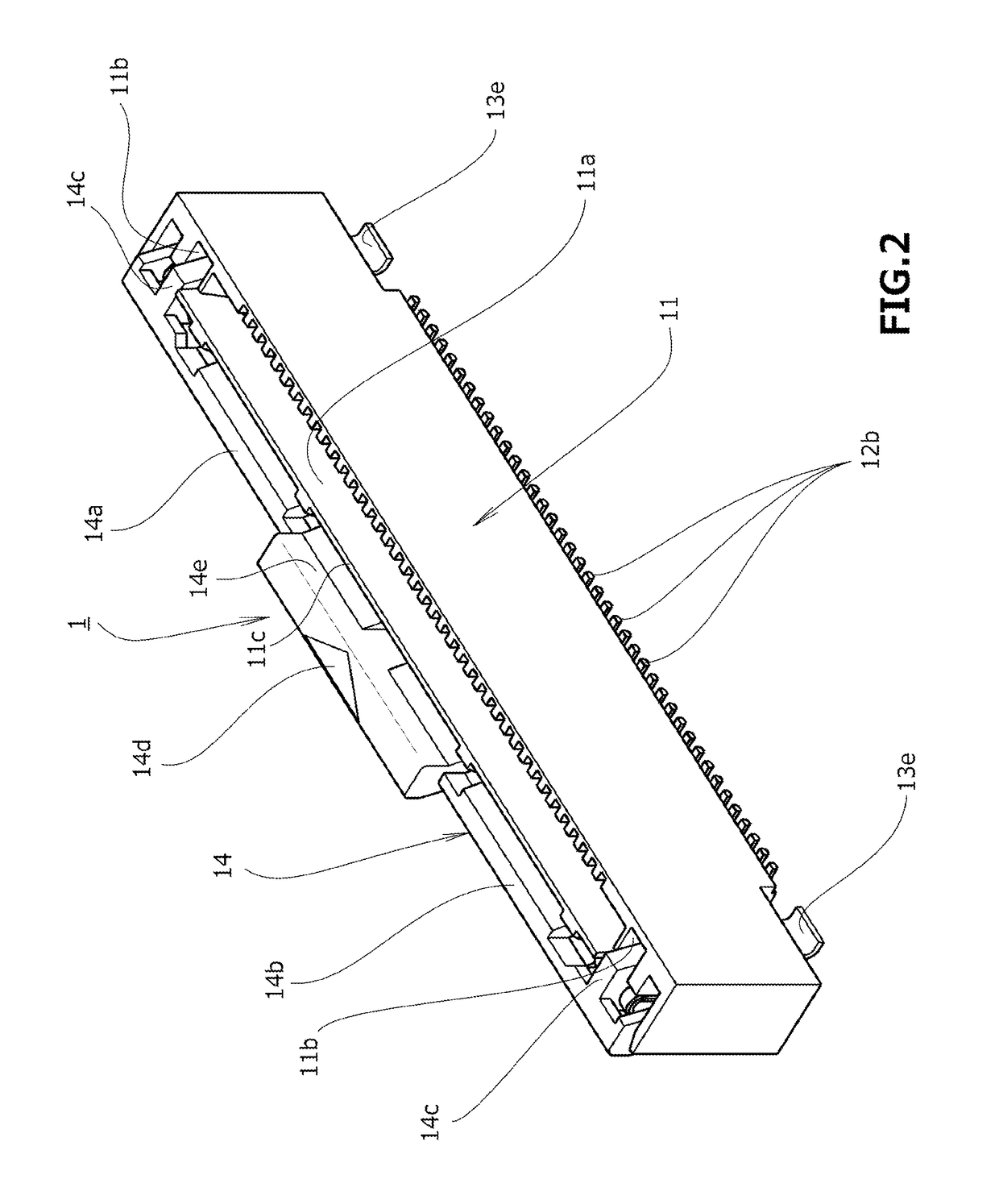
[0050]A connector 1 according to one embodiment of the present invention depicted in FIG. 1 to FIG. 9 is an electric connector mounted by, for example, solder joint or the like, on a circuit wiring board (omitted in the drawings) configuring part of an electronic circuit provided to an electric product. The connector 1 has a housing 11 arranged so as to rise in a direction perpendicular to a main surface of the circuit wiring board substantially horizontally arranged. The housing 11 is formed of an insulating member extending in a narrow elongated shape along the main surface of the circuit wiring board.

[0051]In the following, it is assumed that the main surface of the circuit wiring board (omitted in the drawings) extends in a horizontal state and a direction in which the housing 11 rises from...


PUM


Abstract

For easy removal of a flat-plate-shaped signal transmission medium while reduction in height and size is achieved with a simple structure, a structure is adopted for an electric connector as follows. That is, a release operating part of a lock releasing member which causes a lock member in an engaged state to make a transition to a released state is arranged along an insertion opening. The release operating part and a release acting part are arranged in opposite regions in a radius direction of rotation of a support shaft part. The release operating part can make reciprocating rotations between an initial position away from the insertion opening and an acting position close to the insertion opening. Thus, when a flat-plate-shaped signal transmission medium is removed, the flat-plate-shaped signal transmission medium can be held while the engaged state of the lock member with respect to the flat-plate-shaped signal transmission medium is released by one hand of an operator.

Description

TECHNICAL FIELD OF THE INVENTION[0001]The present invention relates to an electric connector configured to use a lock member to hold a flat-plate-shaped signal transmission medium inserted inside a housing.BACKGROUND OF THE INVENTION[0002]Conventionally, in various electrical appliances and so forth, electric connectors have been widely used for electrically connecting a flat-plate-shaped signal transmission medium such as a flexible flat cable (FFC) or a flexible printed circuit (FPC) to a circuit wiring board. An electric connector of this type is used with a connection terminal part of a conductive contact member being mounted by, for example, solder joint or the like, on a main surface of the circuit wiring board. The flat-plate-shaped signal transmission medium inserted into an insertion opening provided to a housing of the electric connector is electrically connected to the circuit wiring board as being retained in contact with the conductive contact member attached to the hou...

Claims


Application Information

Patent Timeline
Patent Type & Authority Patents(United States)
IPC IPC(8): H01R12/77H01R12/61H01R13/639H01R12/59H01R13/641H01R12/72H01R12/87H01R12/79
CPCH01R12/774H01R12/592H01R12/61H01R13/639H01R13/641H01R12/727H01R12/87H01R12/79H01R12/771H01R13/6335
Inventor MURO, MASATAKA
Owner DAIICHI SEIKO CO LTD
Features
  • R&D
  • Intellectual Property
  • Life Sciences
  • Materials
  • Tech Scout
  • Unparalleled Data Quality
  • Higher Quality Content
  • 60% Fewer Hallucinations
Learn More