Electrochemical multi-cell and method therefor

a technology of electrochemical multi-cells and cell components, applied in the direction of cell components, final product manufacturing, sustainable manufacturing/processing, etc., can solve the problems of increasing cell manufacturing complexity, reducing overall cell amp-hour (ah) capacity, and localized lithium plating, so as to prevent electrical shorting, reduce cell amp-hour (ah) capacity, and high temperature

Active Publication Date: 2018-09-18
A123 SYSTEMS LLC
View PDF9 Cites 0 Cited by
  • Summary
  • Abstract
  • Description
  • Claims
  • Application Information

AI Technical Summary

Benefits of technology

[0004]Several conventional methods of discrete tab attachment are currently employed in the manufacture of electrochemical storage cells, electrochemical capacitors, electrolytic capacitors, dry film capacitors and similar electrical devices. Conventional methods for discrete tab attachment include removing a coating in regions on both sides of a coated electrode and welding tabs to the exposed uncoated regions, and subsequently applying an insulating cover layer over the welded tab and the exposed foil on the opposite side of the electrode from the tab. In other conventional methods, the coating removal step may be avoided by partially coating the electrode surfaces, leaving uncoated coating-free electrode edge foils. Furthermore, tabs may be adhered to or alternately, cut out and formed from uncoated electrode regions. Insulating tape may then be applied to cover the tabs in order to prevent electrical shorting at the tab edges. Conventional methods for providing electrical connection of the electrodes to the wound electrode assembly without discrete tabs include blind through welding of coating-free edge foils to a plate. Electrical connection may also be provided by holding a plate in mechanical compression against the uncoated electrode foil edges.
[0005]The inventors herein have recognized potential issues with the above approaches. Namely, with the use of discrete tabs, electrical current may be channeled to a small area of the tabs at discrete points along the electrode, creating areas that may operate at significantly higher temperature than the remainder of the electrode due to high localized ohmic heating. Furthermore, cell Amp-hour (Ah) capacity is reduced overall due to the uncoated regions for tab attachment, localized differences in the anode to cathode capacity ratio in the uncoated regions may cause localized lithium plating in the case of the Li-ion battery cell chemistry. Further still, cell manufacturing complexity is increased and manufacturing speed is decreased, requiring additional functions to accomplish the coating removal, tab welding and taping operations, and demands a greater financial investment to start up production. Further still, cell manufacturing process speed may be reduced to perform coating removal, tab welding and tab taping, thereby increasing cell manufacturing cost.
[0009]In this way, an electrochemical storage multi-cell having a very large format and providing equivalent or improved electrical and thermal performance and reduced manufacturing costs relative to conventional electrochemical storage multi-cells is provided. Furthermore, the electrochemical storage multi-cell may be produced without welding tabs to individual electrodes, thereby reducing manufacturing time and cost. Further still, cylindrical electrochemical storage multi-cells may be produced with low impedance electrical connections between electrode foils and housing terminals, thereby allowing high power operation while reducing manufacturing cost. Further still, cylindrical electrochemical storage multi-cells with low thermal resistance in relation to one another and increased component sharing may be provided, thereby reducing the number of components and the manufacturing complexity of the electrochemical storage multi-cells, reducing the size of the electrochemical storage multi-cells per unit power, and reducing manufacturing cost (resulting from reduced number of components and handling thereof, and reduced manufacturing complexity).

Problems solved by technology

Furthermore, cell Amp-hour (Ah) capacity is reduced overall due to the uncoated regions for tab attachment, localized differences in the anode to cathode capacity ratio in the uncoated regions may cause localized lithium plating in the case of the Li-ion battery cell chemistry.
Further still, cell manufacturing complexity is increased and manufacturing speed is decreased, requiring additional functions to accomplish the coating removal, tab welding and taping operations, and demands a greater financial investment to start up production.
Further still, cell manufacturing process speed may be reduced to perform coating removal, tab welding and tab taping, thereby increasing cell manufacturing cost.

Method used


Image

  • Electrochemical multi-cell and method therefor
  • Electrochemical multi-cell and method therefor
  • Electrochemical multi-cell and method therefor

Examples


Embodiment Construction

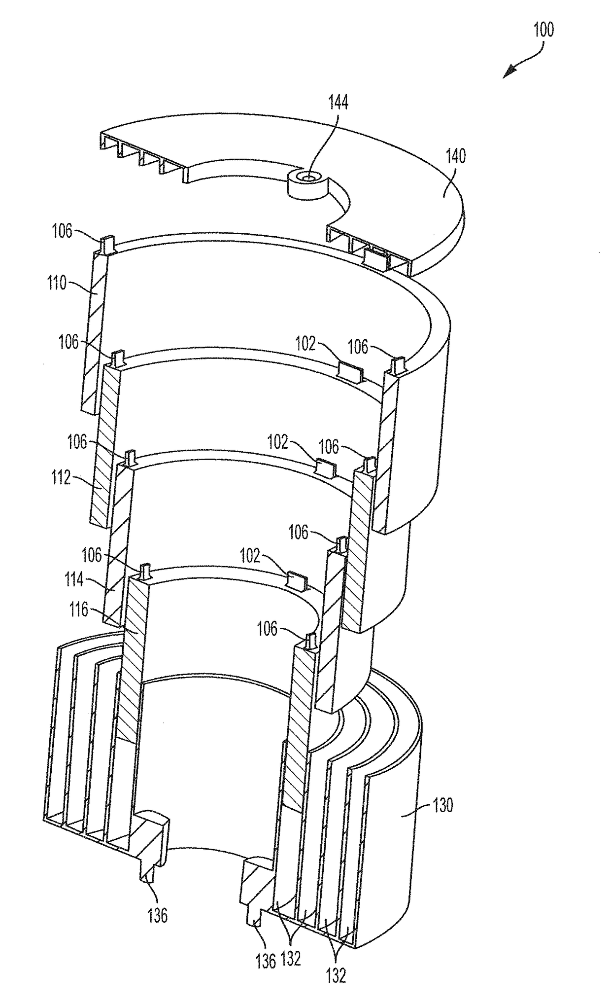
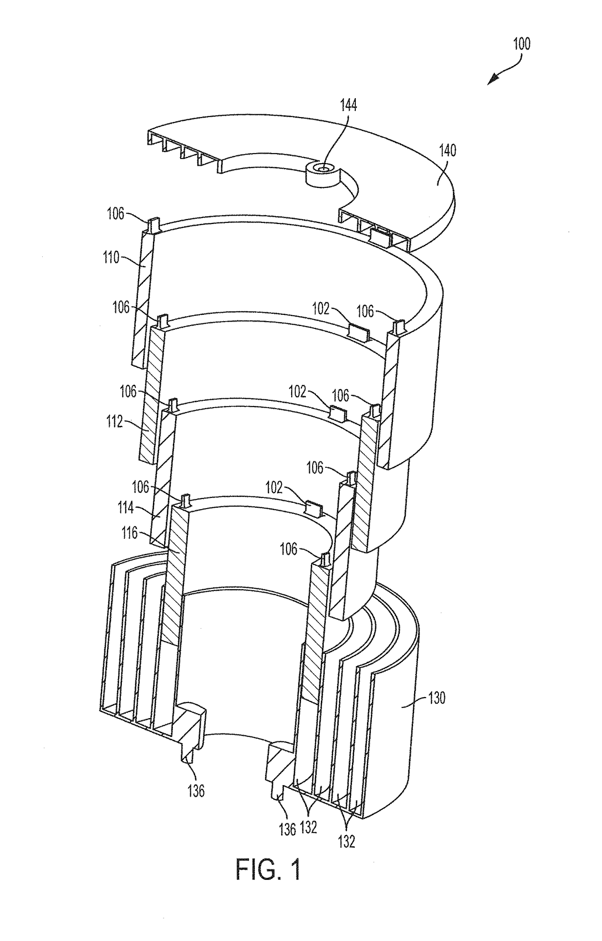
[0029]Aspects of this disclosure will now be described by example and with reference to the illustrated embodiments listed above. Components, process steps, and other elements that may be substantially the same in one or more embodiments are identified coordinately and are described with minimal repetition. It will be noted, however, that elements identified coordinately may also differ to some degree. It will be further noted that unless otherwise noted the drawing figures included in this disclosure are schematic and generally not drawn to scale. Rather, the various drawing scales, aspect ratios, and numbers of components shown in the figures may be purposely distorted to make certain features or relationships easier to see. However, FIGS. 1, 5A-5C, 6-11, 12A, 12B, 13A, and 13B are drawn to scale, although other relative dimensions may be used.

[0030]The present description relates to a cylindrical electrochemical storage multi-cell and a fabrication method thereof providing equiva...


PUM

PropertyMeasurementUnit
included angleaaaaaaaaaa

Abstract

An electrochemical storage multi-cell may comprise: a housing, including a plurality of concentric annular cell chambers; a plurality of electrochemical storage cells, wherein each of the plurality of annular cells are positioned in one of the plurality of annular cell chambers, and the plurality of annular cells are electrically connected in series; and conductive electrolyte filling each of the annular cell chambers.

Description

CROSS REFERENCE TO RELATED APPLICATIONS[0001]This application is the U.S. National Phase of International Patent Application Serial No. PCT / US2015 / 010914, entitled “Electrochemical Multi-Cell And Method Therefor”, filed Jan. 9, 2015, which claims priority to U.S. Provisional Patent Application No. 61 / 925,534, entitled “Electrochemical Multi-Cell and Method Therefor”, filed Jan. 9, 2014, the entire contents of each of which are hereby incorporated by reference in their entirety for all purposes.TECHNICAL FIELD[0002]This disclosure relates to an electrochemical multi-cell, and method therefor, providing equivalent or increased electrical and thermal performance and reduced manufacturing cost relative to conventional devices.BACKGROUND AND SUMMARY[0003]In order to produce a high power cylindrical electrochemical cell with low electrical impedance, current production techniques comprise multiple electrically conducting tabs to be attached, normally by welding, to the electrode substrate...

Claims


Application Information

Patent Timeline
Patent Type & Authority Patents(United States)
IPC IPC(8): H01M2/02H01M10/0587H01M2/30H01M10/0525H01M2/24H01M2/04H01M10/04H01M50/112H01M50/529H01M50/548H01M50/55H01M50/559
CPCH01M2/0242H01M2/046H01M2/24H01M10/0587H01M10/0422H01M10/0525H01M2/30Y02E60/10H01M50/112Y02P70/50H01M50/55H01M50/548H01M50/559H01M50/543H01M50/152H01M50/213H01M50/529
Inventor DAWSON, JAMES E.IJAZ, MUJEEB
Owner A123 SYSTEMS LLC
Why Eureka
Try Eureka